Photoetching device and photoetching method

A technology of lithography and detection devices, which is applied in the field of immersion lithography devices and lithography, and can solve problems such as lack of immediacy and prone to errors

Active Publication Date: 2012-08-22
SVG TECH GRP CO LTD +1
View PDF0 Cites 0 Cited by
  • Summary
  • Abstract
  • Description
  • Claims
  • Application Information

AI Technical Summary

Problems solved by technology

However, this pre-set program is prone to errors during actual operation and does not have immediacy

Method used


Image

  • Photoetching device and photoetching method
  • Photoetching device and photoetching method
  • Photoetching device and photoetching method

Examples


Embodiment Construction

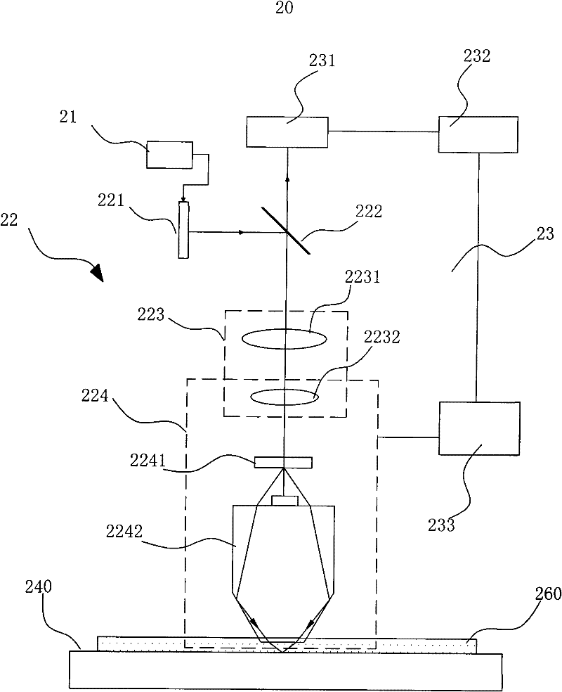
[0034] See figure 2 , figure 2 is a structural schematic diagram of the photolithography apparatus of the present invention. As shown in the figure, the lithography apparatus 20 includes an engraving light source 21 , an optical system 22 and an automatic focusing system 23 . The optical system 21 includes a diaphragm 221 , a partially reflective optical device 222 , an imaging lens group 223 and an interference optical head 224 . Wherein, the aperture 221 is a digital micromirror element or a spatial light modulator, which has an adjustable etching pattern. The imaging lens group 223 includes a first lens group 2231 and a second lens group 2232, the diaphragm 221 is positioned at the front focal plane of the first lens group 223, and the object surface 240 to be engraved is arranged at the back focus of the second lens group 2232 surface, in order to image the pattern formed on the aperture 221 onto the surface 240 of the object to be engraved with optimal resolution.

...


PUM


Abstract

The invention relates to a photoetching device and a photoetching method. The photoetching device is characterized in that a detection device is arranged in the conjugation position of a diaphragm according to the reversibility principle of a light path; the detection device can detect the convergence and imaging information of light rays on the surface of an object to be photoetched; and the quality of photoetching light points is enhanced. At the same time, the photoetching method can realize that automatic focusing can be instantaneously and accurately carried out either the defocusing phenomenon resulted from the unevenness condition of the surface of the object to be photoetched or the defocusing phenomenon resulted from the refractive index change because of filling solution heatingappearing in the etching course by utilizing the photoetching device so that the photoetching quality of movable type exposure can be ensured.

Description

technical field [0001] The invention relates to a photolithography device and a photolithography method, in particular to an immersion type photolithography device and a photolithography method. Background technique [0002] The development of the semiconductor industry is inseparable from lithography technology. The emergence of almost every new generation of integrated circuits is marked by the realization of smaller feature sizes by lithography technology. Therefore, people obtain smaller feature sizes by continuously reducing the exposure wavelength of the lithography machine, increasing the numerical aperture of the projection objective lens, or combining the two. At present, the exposure wavelength of the lithography machine has been reduced from 436nm, 365nm, and 248nm to 193nm, and the liquid immersion technology has also increased the numerical aperture of the projection objective lens from 0.93 to more than 1.3. The IC industry generally believes that the 193nm im...

Claims


Application Information

Patent Timeline
Patent Type & Authority Patents(China)
IPC IPC(8): G03F7/20G03F7/207G03F7/00
Inventor 浦东林胡进张月雨唐灵魏国军周小红陈林森
Owner SVG TECH GRP CO LTD
Why Eureka
Try Eureka