
Analysis evaporator

An evaporator and flow path technology, applied in the field of analytical evaporators, can solve the problems of poor control of flow velocity and flow process, certain safety of operators, splashing or overflow of low-temperature liquid, etc., and achieves strong controllable performance and convenient operation , light weight effect

Active Publication Date: 2012-04-25
陈文选
View PDF3 Cites 0 Cited by
  • Summary
  • Abstract
  • Description
  • Claims
  • Application Information

AI Technical Summary

Problems solved by technology

[0002] Analytical evaporator is used as a rapid extraction equipment for analyzing impurity gas and trace gas content in liquefied gas in the air separation device industry. The analytical evaporator can analyze the hydrocarbons in the main cold box or liquefied gas in the storage tank; the crude argon tower Oxygen (nitrogen, argon) gas content in the pumping liquid, crude krypton xenon (product) bottom hydrocarbons, carbon dioxide, nitrous oxide, nitrogen hydrides such as nitrous oxide in the adsorber, and total hydrocarbons in hydrocarbons, etc. Impurity gas content, as well as trace and trace gas content in high-purity gas separation, provide timely, suitable temperature, appropriate and stable gas source for its online continuous detection analysis or offline sampling analysis. Existing equipment requires operators to The air separation tower or storage tank (tank) is directly sampled through the switch nozzle valve on site. Since the sampling port of the liquefied gas is an ultra-low temperature gas (about -198°C), it is difficult to control the flow rate and flow process, and often the amount of sample gas And back cooling causes the instability of the sample gas source, and at the same time, low-temperature liquid often splashes or overflows during this process, which poses certain safety hazards to operators

Method used


Image

  • Analysis evaporator
  • Analysis evaporator
  • Analysis evaporator

Examples


Embodiment Construction

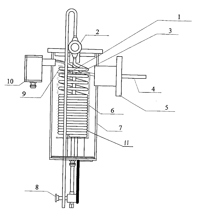
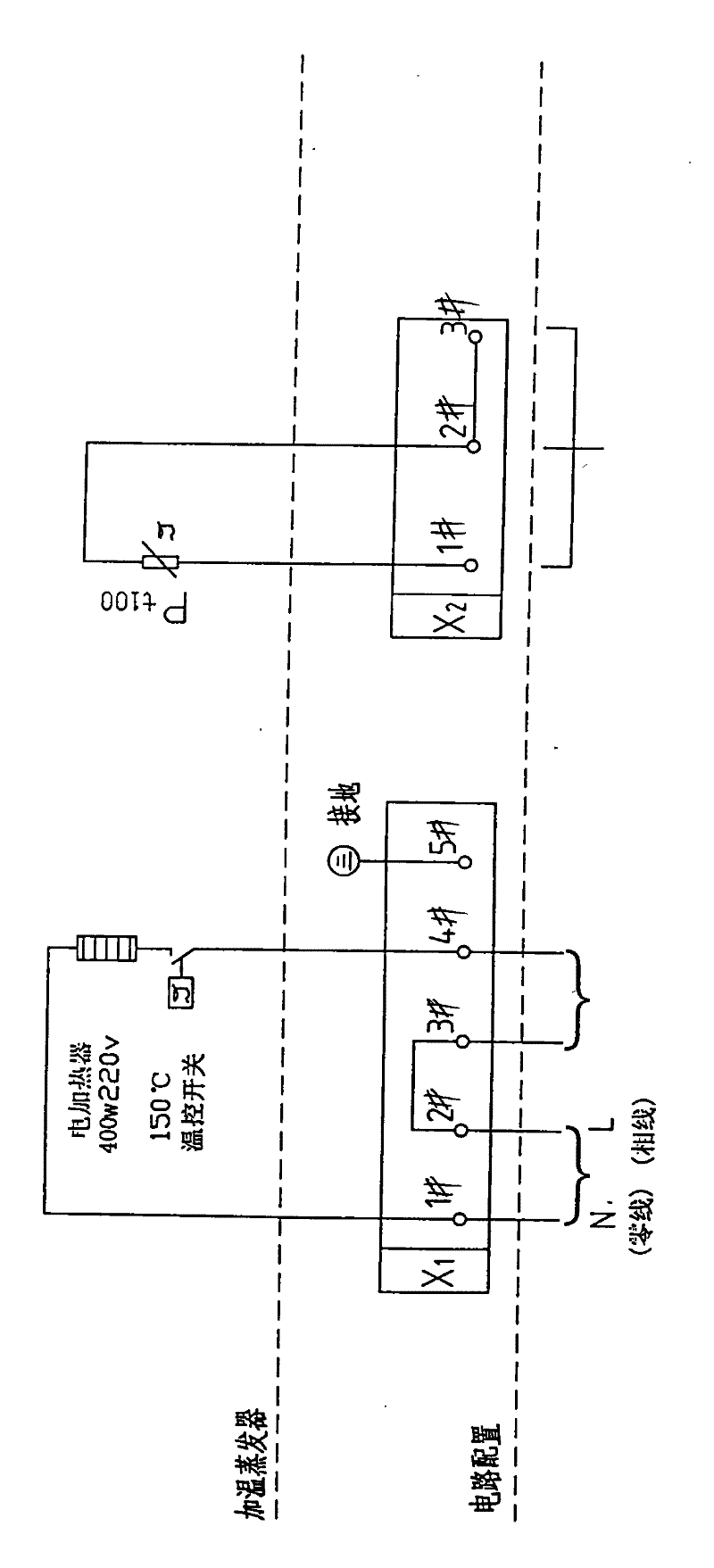
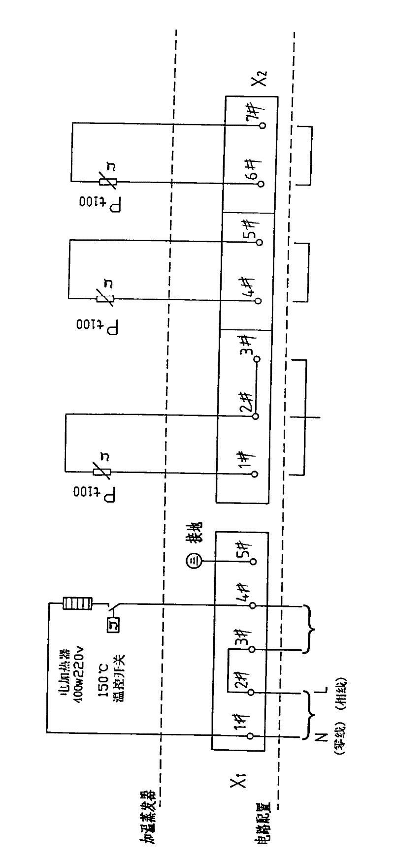
[0011] Control attached figure 1 , which is characterized by an overall structure, with a heating flow path body 6 inside, a Pt100 platinum resistance 1 inserted in the heating flow path body 6, one end of the heating wire 3 is connected in series with the temperature switch K, and the other end of the heating wire is connected to the power supply The terminal X1 is connected; the signal line of the Pt100 platinum resistance is connected to the control signal connection terminal X2; the outer shell 7 is a cylindrical container body, connected to the flange 4, the air inlet connecting pipe 4, the gas output valve 8, the exhaust end valve 2 and The external power supply and signal line are fixed on the shell with junction box 10 .

[0012] The main body 6 of the heating flow path is aluminum cylindrical, and the innermost layer of the main body of the heating flow path is an aluminum cylindrical heating element with an embedded electric heating wire. The long coil 11 is covered ...


PUM


Abstract

The invention provides an analysis evaporator, which is characterized by having an integral structure, wherein a heating flow path main body is arranged in the analysis evaporator; a Pt100 platinum resistor is inserted into the heating flow path main body; one end of an electric heating wire is connected in series with a temperature switch, and the other end of the electric heating wire is connected with a power supply connector; a signal wire of the Pt100 platinum resistor is connected with a control signal connector; a shell is a tube-shaped container; and a connecting flange, an air inlet connecting tube, an air outlet valve, an air-releasing end valve, an external power supply and the signal wire are fixed on the shell by a junction box. The analysis evaporator has the advantages that: the analysis evaporator is directly and fixedly arranged on a sampling wall of an air separation column or at the bottom of a storage tank; and one path (or three paths) of Pt100 resistor (resistors) is (are) arranged in the device to provide a signal for a DCS (analysis room) to set, measure and control the temperature of the heating flow path main body in the device. The analysis evaporator has the characteristics of compact structure, small volume, stable performance, convenience of operation, high controllability, high safety, high practicability, long service life and wide application range.

Description

technical field [0001] The invention relates to an analysis evaporator, which belongs to the technical field of rapid vaporization and extraction of liquefied gas used for analysis in an air separation unit. Background technique [0002] Analytical evaporator is used as a rapid extraction equipment for analyzing impurity gas and trace gas content in liquefied gas in the air separation device industry. The analytical evaporator can analyze the hydrocarbons in the main cold box or liquefied gas in the storage tank; the crude argon tower Oxygen (nitrogen, argon) gas content in the pumping liquid, crude krypton xenon (product) bottom hydrocarbons, carbon dioxide, nitrous oxide, nitrogen hydrides such as nitrous oxide in the adsorber, and total hydrocarbons in hydrocarbons, etc. Impurity gas content, as well as trace and trace gas content in high-purity gas separation, provide timely, suitable temperature, appropriate and stable gas source for its online continuous detection anal...

Claims


Application Information

Patent Timeline
Patent Type & Authority Patents(China)
IPC IPC(8): G01N1/28B01D1/02
Inventor 陈文选
Owner 陈文选
Learn More