
Grid-connected photovoltaic inverter

A technology of inverters and photovoltaics, applied in photovoltaic power generation, single-network parallel feed arrangement, conversion of AC power input to DC power output, etc., can solve problems such as DC injection, grid current distortion, and additional system loss, and achieve Reduced differential mode voltage and current ripple, small output current ripple, and low switching loss

Inactive Publication Date: 2011-02-23
HEBEI UNIV OF TECH
View PDF6 Cites 90 Cited by
  • Summary
  • Abstract
  • Description
  • Claims
  • Application Information

AI Technical Summary

Problems solved by technology

[0004] However, since there is no transformer isolation, there is an electrical connection between the photovoltaic array module and the grid. In addition to causing safety problems, the following two problems may also arise: First, the current input by the inverter to the grid may contain large DC component (that is, DC injection), which causes the shift of the operating point of the distributed transformer in the grid, which may cause transformer saturation; second, if the inverter has a variable common-mode voltage, a common-mode voltage will be generated between the photovoltaic array module and the ground Current (that is, leakage current), common mode current may produce serious conduction or radiation electromagnetic interference, resulting in distortion of the grid current and increasing the additional loss of the system
(3) For transformerless photovoltaic grid-connected inverter systems, an inverter structure that does not generate variable common-mode voltage must be used
[0009] The paper "Multilevel converters for single-phase grid connected photovoltaicsystems-an overview" (IEEE International Symposium on Industrial Electronics, Pertoria, South Africa, 1998.) points out that the use of diode-clamped three-level inverters does not generate common-mode current , and can improve efficiency and reduce ripple, but this structure has DC injection problems

Method used


Image

  • Grid-connected photovoltaic inverter
  • Grid-connected photovoltaic inverter
  • Grid-connected photovoltaic inverter

Examples


Embodiment

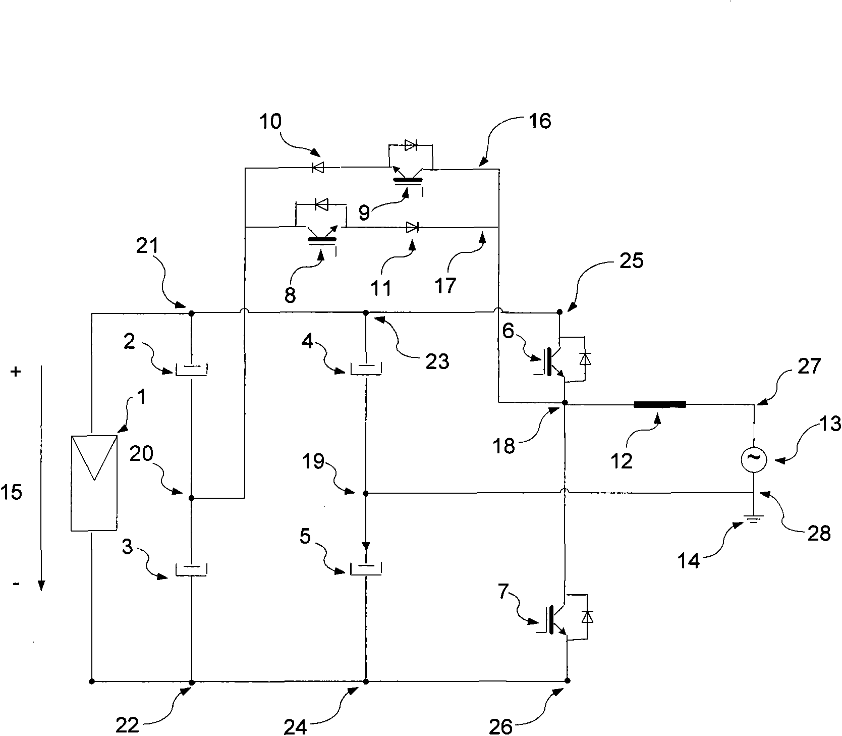
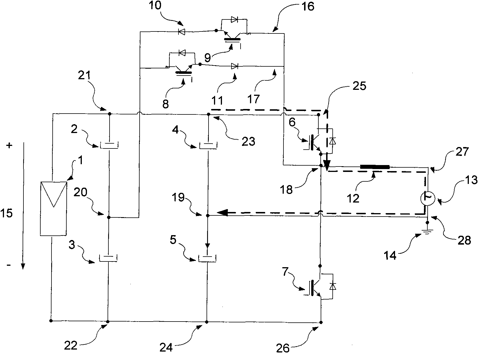
[0040] A photovoltaic grid-connected inverter in this embodiment is composed of a photovoltaic array module, four identical switching tubes, two identical diodes, four identical capacitors, an inductor and a grid.

[0041] The components used in a photovoltaic grid-connected inverter in this embodiment include: 1. Photovoltaic array module, 2. Capacitor, 3. Capacitor, 4. Capacitor, 5. Capacitor, 6. Switch tube, 7. Switch tube, 8. Switch tube, 9. Switch tube, 10. Diode, 11. Diode, 12. Inductor, 13. Power grid and ground wire 14. All switches are insulated gate bipolar transistors IRG4PSC71UD, all diodes are fast recovery diodes HFA25TB60, the capacitance value of the capacitor used is 300uF, the inductance value of the inductor used is 1.5mH, and the model of the photovoltaic array module used is 165(36) P / G1573*824 solar panels are connected in series and parallel, the output voltage can be between 700V and 1100V, the grid voltage is 220V, the grid frequency is 50Hz, the rated...


PUM

PropertyMeasurementUnit
Capacitanceaaaaaaaaaa
Inductanceaaaaaaaaaa

Abstract

The invention discloses a grid-connected photovoltaic inverter and relates to equipment which employs irreversible DC power input conversion as AC power output for a semiconductor device with a control electrode and is used for being used together with a power supply system of a power supply. The equipment consists of a photovoltaic array module, four identical switching tubes, two identical diodes, four identical capacitors, an inductor and a power grid; and the topology ensures not to generate DC component or common mode current for the power grid. Meanwhile, the inverter has low output current ripple and higher efficiency, and overcomes the defects that the conventional full-bridge inverters and other types of transformerless photovoltaic inverters generate DC component in the power grid and generate common mode current or / and higher current ripple. Compared with a half-bridge inverter, the grid-connected photovoltaic inverter reduces the differential mode voltage and current ripple by half.

Description

technical field [0001] The technical solution of the present invention relates to a device for converting the irreversible DC power input of a semiconductor device with a control pole into an AC power output and for use with a power supply system of a power supply, specifically a photovoltaic grid-connected inverter . Background technique [0002] Solar photovoltaic power generation technology is gradually becoming the focus of attention. In 2008, the total global installed capacity of photovoltaic power generation systems reached 5.56GW, of which Spain, Germany, Italy, the United States, South Korea and Japan accounted for more than 96%, an increase of 50% compared with 2007. By the end of 2008, the total installed capacity of photovoltaic power generation systems had reached 13.4GW. Photovoltaic grid-connected systems accounted for about 99% of the total installed capacity in 2008. [0003] The photovoltaic grid-connected power generation system is mainly composed of ph...

Claims


Application Information

Patent Timeline
IPC IPC(8): H02J3/38H02M7/5387
CPCY02E10/563H02M7/487Y02E10/56
Inventor 杨晓光
Owner HEBEI UNIV OF TECH
Learn More