Annular speed reducer

A reducer and ring-type technology, which is applied in the direction of transmission parts, gear transmissions, and components with teeth, etc., can solve the problems of uneven load on the ring plate, small, only within 100, and unbalanced motion. , to achieve the effect of improving internal lubrication, easy manufacturing and low cost, and widely popularized value

Inactive Publication Date: 2011-03-02
CHONGQING IRON & STEEL (GRP) CO LTD
View PDF6 Cites 6 Cited by
  • Summary
  • Abstract
  • Description
  • Claims
  • Application Information

AI Technical Summary

Problems solved by technology

[0003] However, the three-ring reducer of the prior art still has some disadvantages in use: the main reason is that the three ring plates with the same irregular shape are arranged side by side with a phase difference of 1 2 Oo, and the ring plates are equivalent to the double crank mechanism. Due to the irregular shape and uneven force of the connecting rod, the centrifugal force is large. Although the centrifugal force can be offset, the additional moment generated by the centrifugal force of the ring plate is difficult to offset. During operation, the ring plate is unevenly loaded and the movement is unbalanced. When the upper limit of the input speed of the ring plate is exceeded, the vibration and noise are high; in addition, the speed of the single-stage reducer is relatively small, only within 100, and the volume is large, and the input shaft and output shaft cannot be arranged in the same direction or vertically. The use requirements of various working conditions, so its application range is limited; at the same time, it cannot meet the needs of deceleration transmission in some special fields

Method used


Image

  • Annular speed reducer
  • Annular speed reducer
  • Annular speed reducer

Examples


Embodiment Construction

[0020] The specific implementation manner of the present invention will be described in detail below in conjunction with the accompanying drawings.

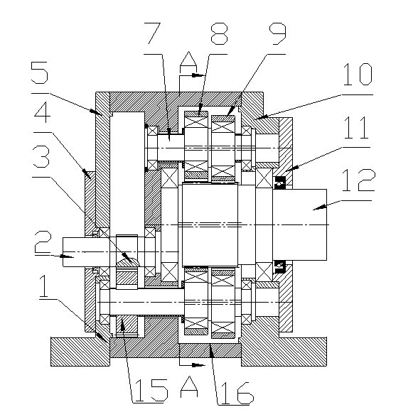
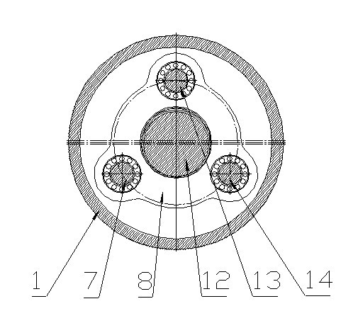
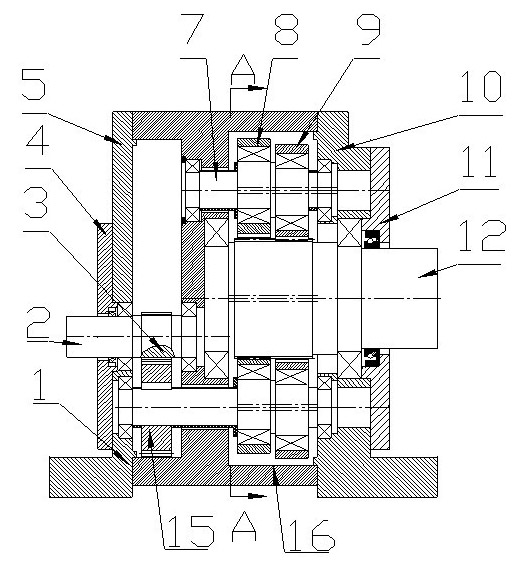
[0021] see figure 1 , figure 2 Schematic diagram of the structure of the present invention, the ring-type reducer of the present invention includes a reducer casing 1 and an input shaft 2, a driving gear 3 is installed on the input shaft 2, and the input shaft 2 drives the driving gear 3 to rotate synchronously; Inside the body 1, there are three eccentric shafts, i.e. the first eccentric shaft 7, the second eccentric shaft 13, and the third eccentric shaft 14. The axes of the three eccentric shafts are parallel to each other and arranged in an equilateral triangle; Or two, or three driven gears 15 are installed on the eccentric shafts, one or two or three driven gears 15 can mesh with the driving gear 3, and the driving gear 3 drives one, or two, or three eccentric shafts when rotating. The driven gear 15 installed on the sha...


PUM


Abstract

The invention discloses an annular speed reducer which comprises a speed reducer box and an input shaft, wherein, the input shaft is equipped with driving gears; the speed reducer box is internally equipped with three eccentric shafts with parallel axes, and the three eccentric shafts are arranged in an equilateral triangle shape; driven gears are arranged on one or two or three eccentric shafts and meshed with the driving gears for synchronous rotation; a first annular plate and a second annular plate are equipped with three bearing holes which are distributed in an equilateral triangle shape and equipped with bearings, the three eccentric shafts pass through the bearing holes respectively, and the first annular plate and the second annular plate are supported on the three eccentric shafts via the bearings; and internal teeth are arranged at central positions of the first annular plate and the second annular plate and meshed with external teeth on an output shaft so as to drive the output shaft to rotate. The two annular plates have the same shape and the same mass and the phase difference of the annular plates in dynamic engagement is 180omicron, thereby counteracting the centrifugal force of the annular plates and basically counteracting the additional moment generated by the centrifugal force so as to realize balance of force and moment. The speed reducer has the advantages of greater transmission and wide use.

Description

technical field [0001] The invention relates to a reducer in the field of mechanical power transmission, in particular to a ring type reducer. Background technique [0002] In the field of modern industry, reducer equipment with less tooth difference transmission has been widely used, and the three-ring reducer is a typical example. Large size, long service life, convenient maintenance, high cost performance, etc., have been widely used in metallurgy, mining, lifting transportation, construction, petrochemical, textile printing and dyeing and other industries, and have formed a series of products, and in many fields, replaced hard tooth Surface planetary reducer, cycloid reducer, cylindrical gear reducer and worm gear reducer. [0003] However, the three-ring reducer of the prior art still has some disadvantages in use: the main reason is that the three ring plates with the same irregular shape are arranged side by side with a phase difference of 1 2 Oo, and the ring plates...

Claims


Application Information

Patent Timeline
Patent Type & Authority Applications(China)
IPC IPC(8): F16H1/22F16H57/02F16H57/023
CPCF16H1/32
Inventor 黄健
Owner CHONGQING IRON & STEEL (GRP) CO LTD
Why Eureka
Try Eureka