

Rotating spindle box for conical part machining
A technology of parts processing and spindle box, which is applied in the field of rotating spindle box for conical parts processing, can solve the problems that workpieces with large angles cannot be processed, the surface quality of workpieces is difficult to guarantee, and the labor intensity of operators is high, etc., so as to achieve high work efficiency, Guaranteed processing quality and simple structure
- Summary
- Abstract
- Description
- Claims
- Application Information
AI Technical Summary
Problems solved by technology
Method used
Image

Examples
Embodiment Construction
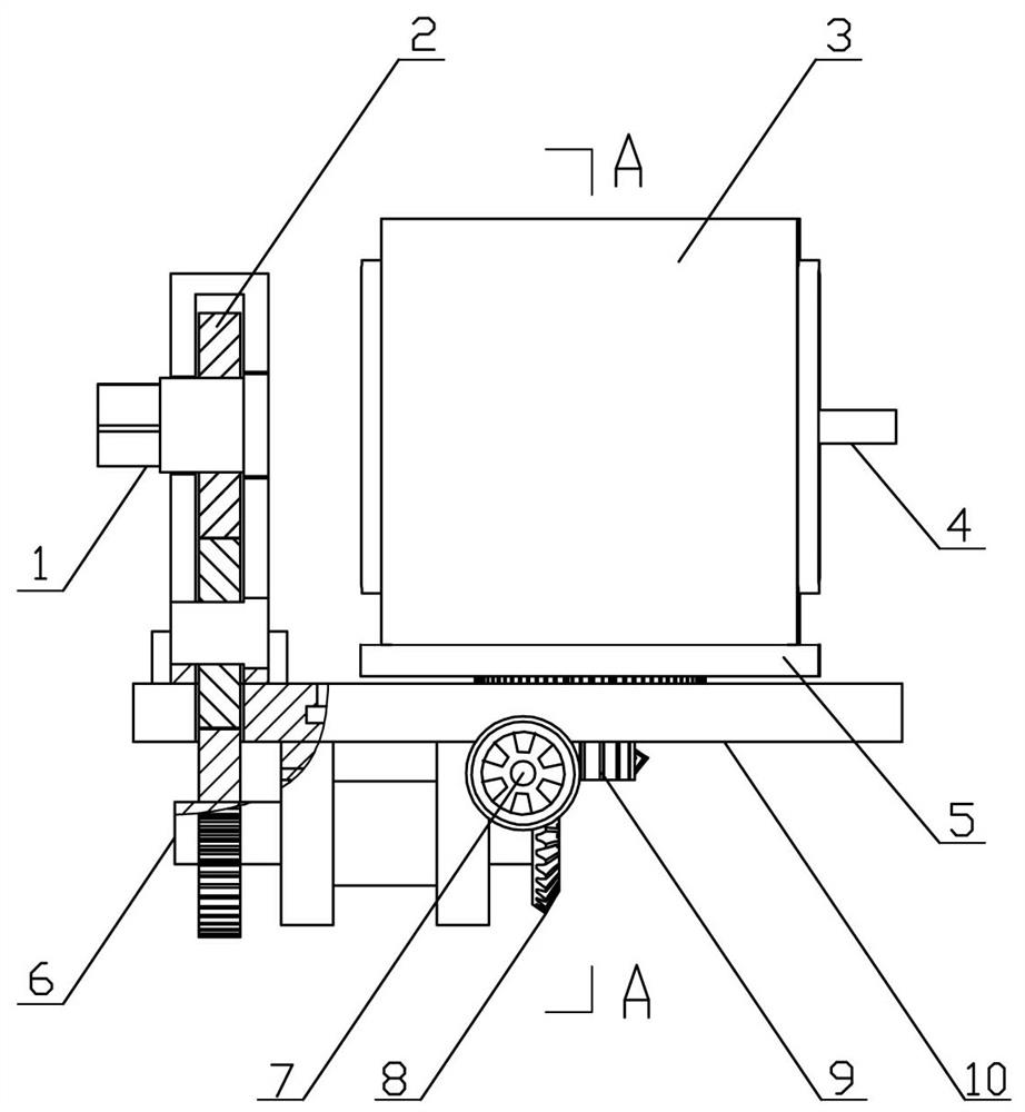
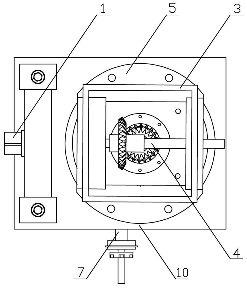
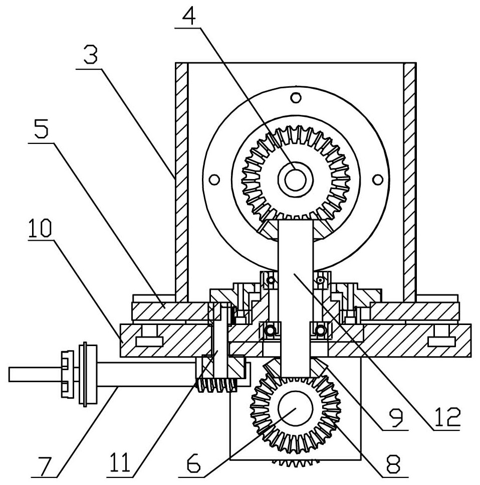
[0029] figure 1 , figure 2 , image 3 , Figure 4 It is a schematic diagram of a rotating headstock for machining conical parts. A rotating headstock for processing conical parts includes a base and a rotating box on the upper part of the base. The left elevation of the base is provided with an input shaft, which passes through two A cylindrical gear drives the horizontal shaft to rotate, the right end of the horizontal shaft is provided with a bevel gear, the right elevation of the rotating box is provided with an output shaft, and the left end of the output shaft is provided with a bevel gear; The bevel gear is matched with the bevel gear at the left end of the output shaft, and the bevel gear at the lower end of the vertical shaft is matched with the bevel gear at the right end of the horizontal axis.
[0030] A worm and a worm wheel are arranged under the base. The worm drives the worm wheel to drive the worm wheel shaft to rotate. The upper end of the worm wheel shaft...
PUM
 Abstract
Description
Claims
Application Information