Method for treating sewage by utilizing grid aeration tank

An aeration tank and sewage technology, which is applied in sustainable biological treatment, chemical instruments and methods, and multi-stage water/sewage treatment, etc., can solve the problems of low utilization rate of dissolved oxygen, high energy consumption for aeration, and save aeration. Energy consumption, improved oxygen transfer rate, high activity effect

Inactive Publication Date: 2011-03-16
HARBIN UNIV OF SCI & TECH
View PDF3 Cites 7 Cited by
  • Summary
  • Abstract
  • Description
  • Claims
  • Application Information

AI Technical Summary

Problems solved by technology

[0004] The purpose of the present invention is to solve the problem that the existing plug-flow activated sludge method does not use grid aeration to treat sewage, so that the u...

Method used


Image

  • Method for treating sewage by utilizing grid aeration tank
  • Method for treating sewage by utilizing grid aeration tank

Examples


specific Embodiment approach 1

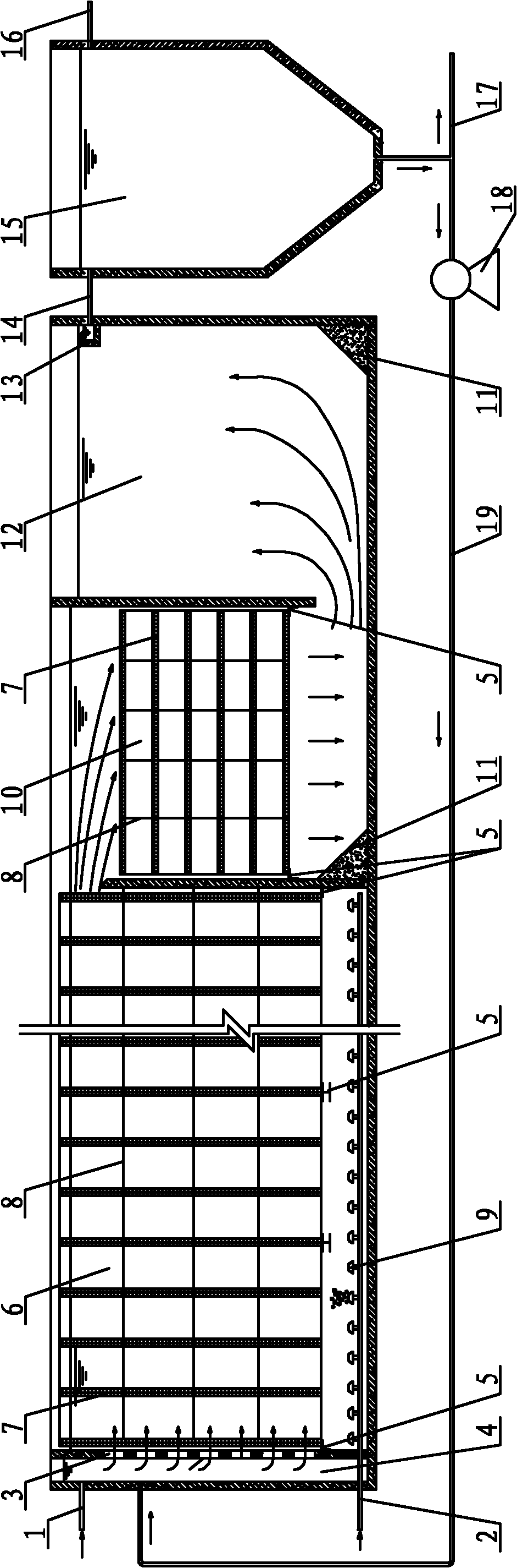
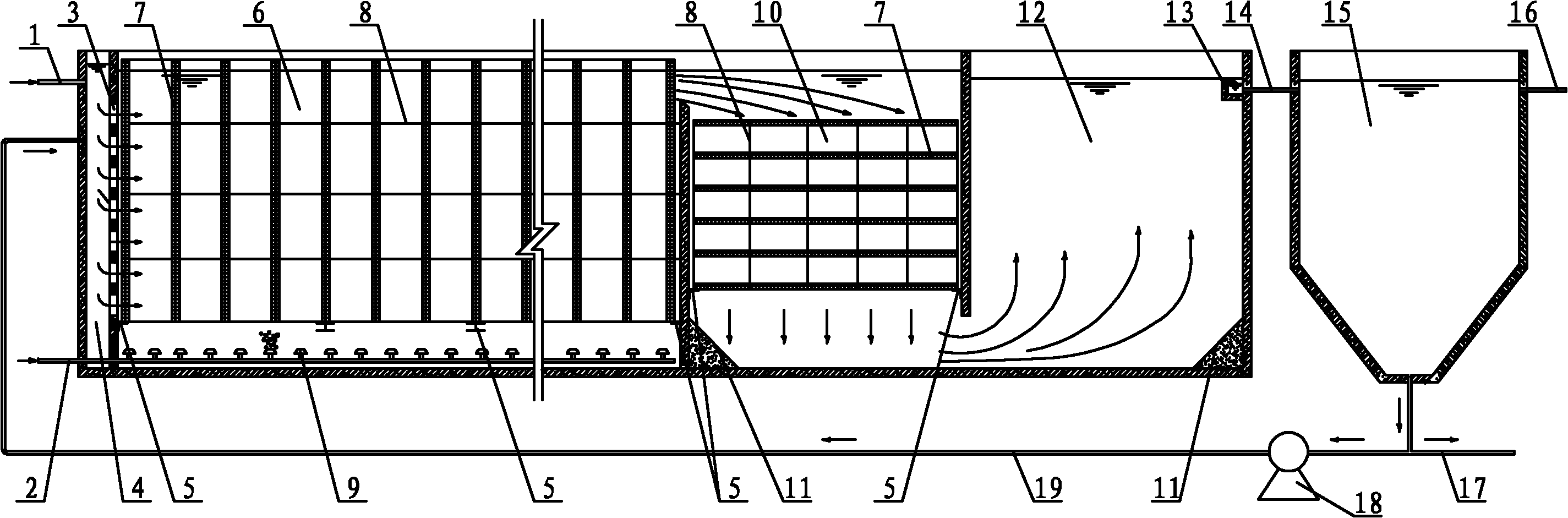
[0008] Specific implementation mode one: combine figure 1 Describe this embodiment, this embodiment is realized by following steps: Step 1, put into sewage: sewage flows into water distribution pool 4 by water inlet pipe 1, flows into the cross section of vortex biochemical pool 6 evenly through the water distribution hole 3 on the water distribution pool 4 On the surface, the flow velocity of the through hole is 0.08m / s~0.12m / s; step 2, aeration process: the sewage flows through the vertically placed multi-layered eddy current biochemical pool 6 under the action of the driving force and inertial force of the subsequent water flow. The grid 7 forms a horizontal flow. At this time, the activated sludge in the vortex biochemical tank 6 is in a suspended state, and the residence time of the sewage in the vortex biochemical tank 6 is 1.5h to 4.0h. The air diffused from the aeration head 9 is Gradually rise from the lower part to the surface of the water body, and the amount of air...

specific Embodiment approach 2

[0011] Specific implementation mode two: combination figure 1 To illustrate this embodiment, in the vertically placed multi-layer grid 7 in step 2 of this embodiment, the distance between two adjacent grids 7 is 0.5m to 1.0m, and the shape of each grid 7 is Circular, regular polygon or rectangular, the diameter of the inscribed circle of each grid 7 is controlled at 0.045m~0.065m. The mixed liquid can be mixed horizontally and vertically within this interval, which is beneficial to the redistribution of dissolved oxygen, organic substrate and activated sludge on the entire cross-section of the tank, avoiding aeration dead zones, and improving the utilization of the aeration head Rate. Other steps are the same as in the first embodiment.

specific Embodiment approach 3

[0012] Specific implementation mode three: combination figure 1 To illustrate this embodiment, in the horizontally placed multi-layer grid 7 in step 3 of this embodiment, the distance between two adjacent grids 7 is 0.4m to 0.6m, and the shape of the hole of each grid 7 is a circle shape, regular polygon or rectangle, and the diameter of the inscribed circle of each grid 7 is controlled at 0.045m to 0.065m. The mixed liquid can be flocculated in this interval, which is beneficial to dissolved oxygen, organic substrate and activated sludge. Other steps are the same as in the first embodiment.

[0013] Specific implementation mode four: combination figure 1 To describe this embodiment, in Step 3 of this embodiment, a diversion slope 11 is provided at the bottom corner of the vortex flocculation tank 10 . The diversion slope 11 can be poured concrete or bricks twice, and the diversion slope 11 is to prevent the formation of sludge dead ends. Other steps are the same as in the...


PUM


Abstract

The invention relates to a method for treating sewage by utilizing a grid aeration tank, and relates to a method for the purification treatment of sewage, which aims to solve the problems of low utilization rate of activated sludge on dissolved oxygen and high energy consumption of aeration during running due to lack of grid aeration in sewage treatment by the conventional plug flow activated sludge method. The method comprises the following steps of: 1, allowing sewage to flow in, wherein the flow rate that the sewage flows through holes is 0.1 m/s; 2, performing aeration, namely allowing the sewage to flow through a multi-layer grid arranged in a vortex biochemical pond vertically to form horizontal flow, wherein the retention time of the sewage in the vortex biochemical pond is 2 hours, and air amount blasted from an aerator is in an amount which is 4 times treated water volume; 3, performing the flocculation process for 6 minutes by taking zoogloea as a flocculating agent and the multi-layer grid arranged horizontally as flocculation equipment, wherein the flow rate that mixed solution flows in the multi-layer grid is 0.08 m/s; 4, performing secondary flocculation process for 9 minutes; and 5, separating mud from water, and precipitating for 1.2 hours. The method is used for the sewage treatment.

Description

technical field [0001] The invention relates to a sewage purification treatment method. Background technique [0002] At present, large-scale sewage treatment projects mostly use plug-flow aerobic activated sludge methods, such as A / O, A / A / O, etc. The plug-flow process can increase the degradation time of organic matter in sewage, and can form a microbial ecosystem from low-level to high-level along the flow direction, which is conducive to improving the removal rate of organic matter. However, the push-flow process also has many disadvantages, such as: short-flow of water is prone to occur, which reduces the utilization rate of the tank body and causes waste of land occupation; the water flow state in the push-flow aeration tank is basically a laminar flow state, and the Reynolds number Smaller, the stirring and mixing effect of the water flow on the airflow, organic matter and activated sludge in the water body is weak, and the above three-phase substances cannot be evenl...

Claims


Application Information

Patent Timeline
IPC IPC(8): C02F9/14C02F3/12
CPCY02W10/10
Inventor 艾恒雨
Owner HARBIN UNIV OF SCI & TECH
Why Eureka
Try Eureka