
Coal separating equipment with multiple combustors and parent-son pipes

A technology with multiple burners and separation equipment, which is used in combustible gas heating coke ovens, special forms of dry distillation, petroleum industry, etc. properties and stability, ease of storage and utilization, and the effect of reducing water content

Active Publication Date: 2011-03-16
HENAN DRAGON INTO COAL TECH CO LTD
View PDF2 Cites 8 Cited by
  • Summary
  • Abstract
  • Description
  • Claims
  • Application Information

AI Technical Summary

Problems solved by technology

[0005] At present, there are mainly two types of commonly used coal decomposition equipment. One is the shaft kiln structure, which burns flue gas and combustible gas produced by coal, which makes the combustible gas have low purity and low added value, and some of it is discharged, causing A lot of waste of resources and pollution of the environment
Another type of vertical kiln is that the coal blocks are placed on a partition with holes, and there is a heater above the coal block. Because the coal blocks on the partition have a certain accumulation thickness, they cannot be heated and decomposed evenly, and the decomposed gas needs to be used to Circular heating, decomposition, and more importantly, because of the existence of a large number of circulation vent holes on the coal separator, coal powder will leak from the vent holes, so when coal powder needs to enter the shaft kiln, it needs to be processed into coal lumps first, Therefore, pulverized coal cannot be directly used for kiln body separation, which correspondingly increases the cost of pulverized coal decomposition and reduces economic benefits

Method used


Image

  • Coal separating equipment with multiple combustors and parent-son pipes
  • Coal separating equipment with multiple combustors and parent-son pipes
  • Coal separating equipment with multiple combustors and parent-son pipes

Examples


Embodiment Construction

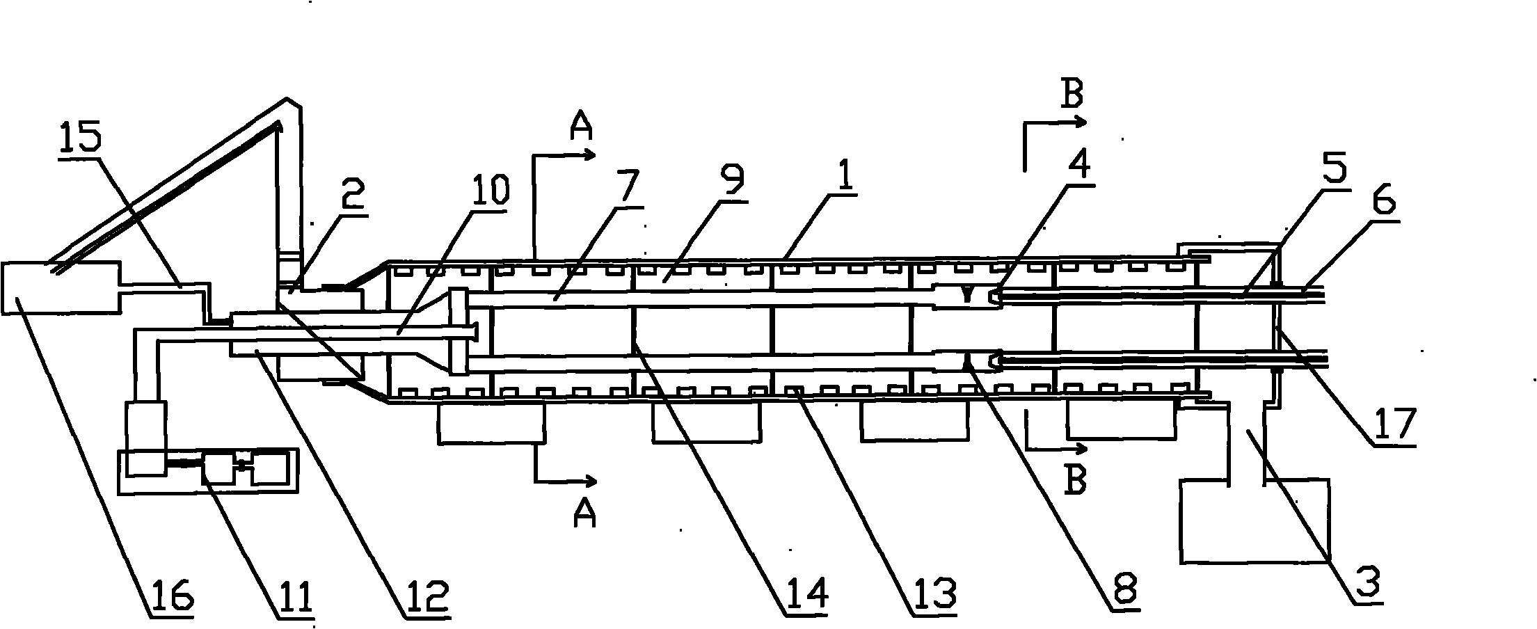
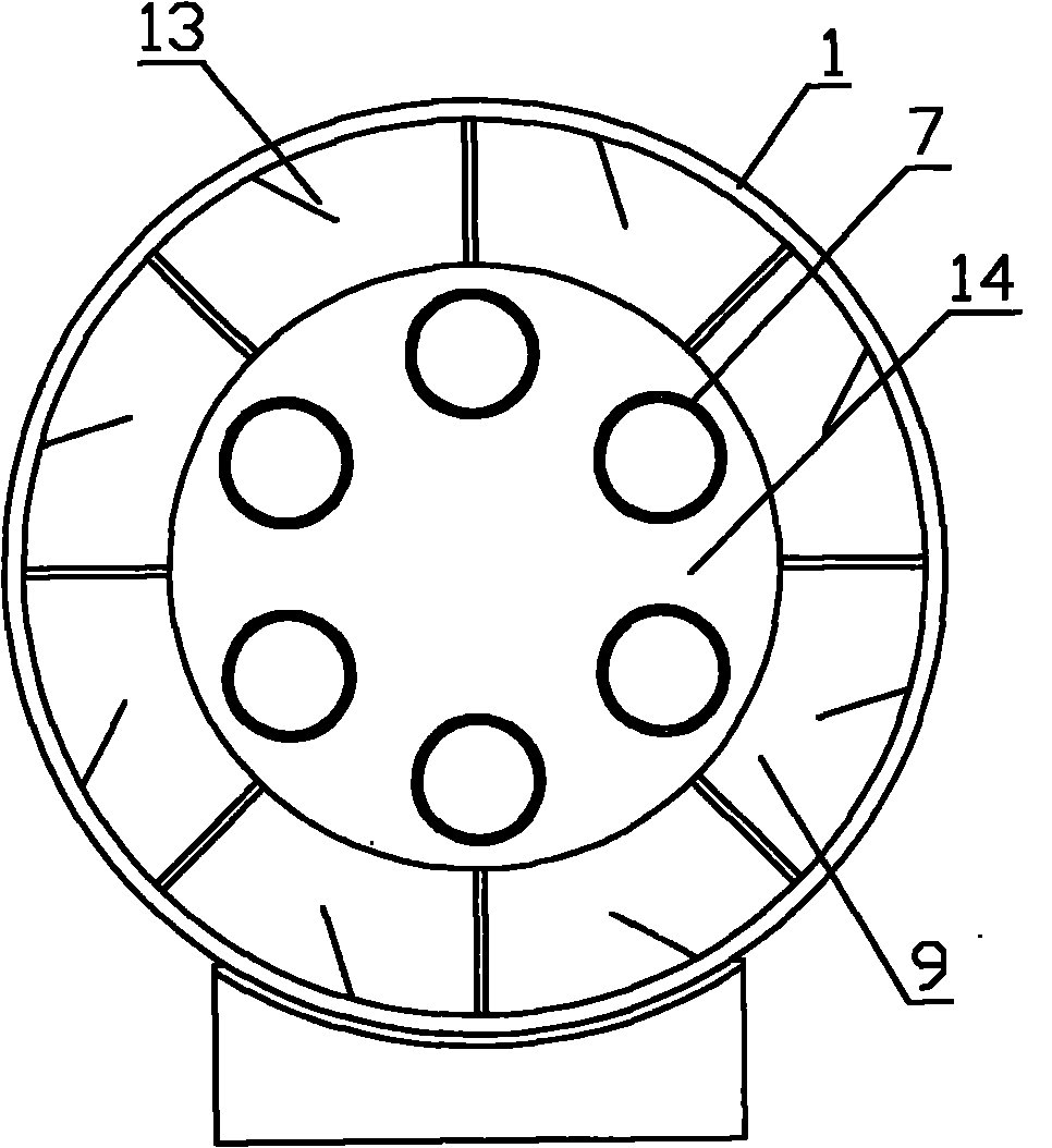
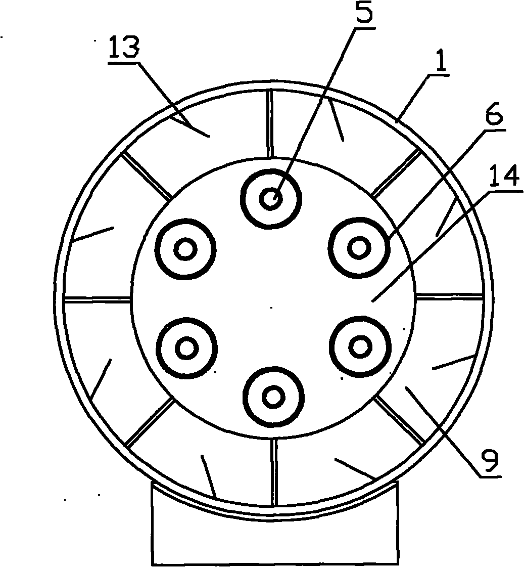
[0018] Such as figure 1 , 2 , 3 shows: a kind of coal material multi-burner sub-pipe separation equipment, including a horizontally arranged sealed rotary kiln body 1, the rotary kiln body 1 includes a feed port 2, a discharge port 3, the rotary kiln body 1 The kiln body 1 is provided with close-packed burners 4 along the direction of the kiln body, and one end of the close-packed burners is provided with close-packed gas intake pipes 5 and close-packed air intake pipes 6, wherein the gas intake pipes are inside the cavity and the air intake pipes are outside. The other end of the close-packed burner is provided with a close-packed flame heat dissipation pipe 7, and an igniter 8 is provided in each burner, and the close-packed burner 4 communicates with the corresponding close-packed gas inlet pipe 5. The row burner 4 communicates with the corresponding close-pack air intake pipe 6, and the close-pack burner communicates with the corresponding close-pack flame heat radiation ...


PUM


Abstract

The invention discloses coal separating equipment with multiple combustors and parent-son pipes, comprising a horizontal sealed rotary kiln body, wherein the rotary kiln body is provided with densely arranged combustors inside; one end of the combustors is connected with corresponding densely arranged gas inlet pipes and air inlet pipes; the gas inlet pipes are arranged in the inner cavities and the air inlet pipes are arranged in the outer cavities; the other end of the combustors is provided with densely arranged radiating pipes; the cavities formed among the combustors, the air inlet pipes, the radiating pipes and the inner wall of the rotary kiln body are used as coal propelling and separating channels; the rotary kiln body is provided with a coal decomposed gas collecting pipe; the densely arranged radiating pipes are communicated with a flame gas gathering pipe; and the flame gas gathering pipe extends out of the rotary kiln. The equipment can rapidly and efficiently decompose and separate the powdered coal, fully saves and utilizes the energy, greatly improves the utilization ratio and level of the coal resources and brings vast economic and social benefits for the whole society.

Description

technical field [0001] The invention belongs to the technical field of comprehensive utilization of coal materials, energy saving and emission reduction, and in particular relates to a coal material multi-burner sub-master pipe separation device. Background technique [0002] Among the known technologies, there are those that use coal to produce gas, some that use coal to produce natural gas, and those that use coal for high-temperature, medium-temperature, and low-temperature coking and gas production. Screening block materials will increase the cost of raw materials, or the calorific value of the produced gas is not high, the added value is not large, and the economic and social benefits are not significant. The heating method of the furnace can be divided into external heating type, internal heating type and internal heating and external heating mixed type. The heating medium of the external heating furnace is not in direct contact with the raw materials, and the heat is...

Claims


Application Information

Patent Timeline
Patent Type & Authority Applications(China)
IPC IPC(8): C10B53/04C10B57/10C10B21/10C10B47/00
Inventor 朱书成王希彬黄祥云曹国超刘伟李明德李晓阳
Owner HENAN DRAGON INTO COAL TECH CO LTD
Learn More