Steel wire rope for rotary drilling machine and preparation method thereof

A technology of steel wire rope and rotary excavator, applied in the field of steel wire rope, which can solve the problems of reduced service life, low breaking force, and easy wear of hoisting, and achieve the effects of increased service life, strong wear resistance, and increased effective area

Inactive Publication Date: 2011-03-16
JIANGSU SAFETY STEEL WIRE ROPE
View PDF0 Cites 12 Cited by
  • Summary
  • Abstract
  • Description
  • Claims
  • Application Information

AI Technical Summary

Problems solved by technology

The current steel wire ropes for rotary excavators, such as 35W×7 series steel wire ropes, etc., have low breaking force, a

Method used


Image

  • Steel wire rope for rotary drilling machine and preparation method thereof
  • Steel wire rope for rotary drilling machine and preparation method thereof

Examples


Embodiment 1

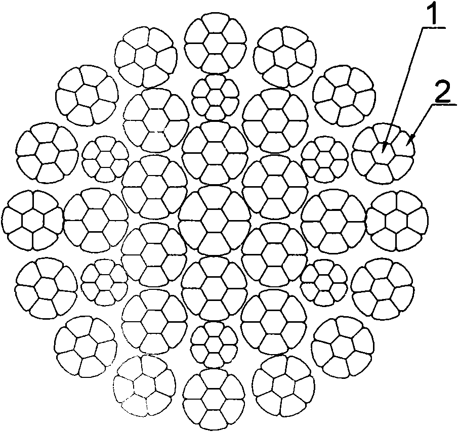
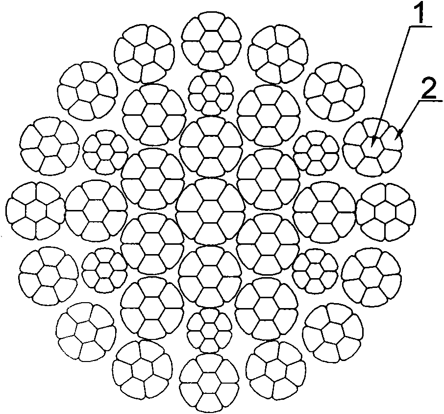
[0026] Such as figure 1 As shown, a steel wire rope for a rotary excavator of the present invention has a specification model of 28NATDL1916AK 1960. It is a fully compacted steel wire rope formed by twisting a central strand wrapped by three layers of strands, wherein the twist direction of the outer strands is the same as The twist direction of the inner two layers of strands is opposite, and each strand is composed of 6 outer layer steel wires 2 wrapped around a central steel wire 1, wherein the outer layer steel wire 2 is approximately trapezoidal, the central steel wire 1 is approximately regular hexagonal, and the inner steel wire and steel wire in surface contact. The steel wire rope of the above structure is formed by twisting twice in a semi-Walington structure of 35 strands. The wire rope is smooth, with a nominal diameter of 28mm and a nominal tensile strength of 1960Mpa.

Embodiment 2

[0028] The preparation method of the steel wire rope for rotary excavator of the present invention is to use the production method of die drawing to cold-draw the steel wire rope strands with a mold when twisting the strands, change the shape of the steel wires in the strands but basically not change the cross-sectional area of ​​the steel wires, and make the strands inside the strands There is a surface contact between the steel wire and the steel wire, and then the rope is closed.

[0029] At the same time, when producing the rope, oil is injected into the strands, and the steel wire rope goes through the oil pan. The inside of the steel wire rope is also filled with grease, and the oil content of the whole rope is increased, which further improves the fatigue resistance of the steel wire rope and meets the requirements of the steel wire rope for rotary excavators. requirements.


PUM

PropertyMeasurementUnit
Nominal diameteraaaaaaaaaa
Tensile strengthaaaaaaaaaa

Abstract

The invention discloses a steel wire rope for a rotary drilling machine and a preparation method thereof. The steel wire rope is a fully pressed solid-strand steel wire rope by twisting three layers of strands around a central strand; each strand is formed by twisting 6 outer-layer steel wires around a central steel wire; the steel wires on the outer layer are approximately trapezoid; the central steel wire is approximately hexagonal; and steel wires in the strands are in surface contact with the steel wires, wherein the twist direction of strands of the steel wire rope on the outer layer is opposite to the twist direction of strands on two inner layers, and oil is filled in the steel wire rope. In the preparation method of the steel wire rope for the rotary drilling machine of the invention, cold drawing is performed on steel wire rope strands by using a die when the strands are twisted by utilizing a production mode of die drawing, the shape of the steel wires in the strands is changed but the cross section area of the steel wires is basically not changed to ensure that the steel wires in the rope strands are in surface contact with the steel wires, and stranding is performed; and simultaneously a mode of spraying oil on the strands and allowing the steel wire rope to pass through an oil pan is adopted during the production. Compared with those of the prior art, the wear resistance, the fatigue resistance, the rotation resistance and the entire tensile force of the steel wire rope for the rotary drilling machine are all remarkably improved.

Description

technical field [0001] The invention relates to a steel wire rope, in particular to a steel wire rope for a rotary excavator and a preparation method thereof. Background technique [0002] The working environment of the rotary excavator is very harsh, so the requirements for the wire rope are particularly high. Current steel wire ropes for rotary excavators, such as 35W×7 series steel wire ropes, etc., have low breaking force, and are easily worn after a long contact time with hoisting and pulleys during use, and the service life is greatly reduced. Contents of the invention [0003] One object of the present invention is to propose a steel wire rope for rotary excavators with better breaking tension and wear resistance in view of the above-mentioned defects in the prior art. [0004] Another object of the present invention is to provide a method for preparing the above-mentioned steel wire rope for a rotary excavator. [0005] The technical scheme for realizing the abov...

Claims


Application Information

Patent Timeline
IPC IPC(8): D07B1/08D07B7/12
Inventor 过惠成华正
Owner JIANGSU SAFETY STEEL WIRE ROPE
Why Eureka
Try Eureka