Method and instrument for detecting oil gas recovery system of gas station

A technology of oil and gas recovery system and detection method, which is applied in the direction of instruments, measuring the rate of increase and deceleration of fluids, and measuring devices, etc., can solve the problem that the patent does not have data storage, printing, and transmission functions, lacks automatic detection, intelligent detection functions, and has no Seeing problems such as problems, to achieve the effect of convenient standardized management, reliable test results, and convenient portability

Inactive Publication Date: 2011-03-30
中机生产力促进中心有限公司
View PDF5 Cites 19 Cited by
  • Summary
  • Abstract
  • Description
  • Claims
  • Application Information

AI Technical Summary

Problems solved by technology

[0006] According to the technical characteristics of the present invention, the relevant patent database has been retrieved, and no related invention patents have been found in the gas station oil gas recovery detection method and instrument. The related utility model patents include "oil gas recovery comprehensive detector" (ZL200820004655.6), which was established by our unit in 2008 It was applied for in January 2010, but the patent does not have the functions of data storage, printing, and transmission, and lacks the functions of automatic detection and intelligent detection. Item indicators”, the oil and gas recovery detection method with the functions of “automatic storage, transmission and printing of detection data”, and related reports on the integrated intelligent detector composed of explosion-proof circuit and closed circuit

Method used


Image

  • Method and instrument for detecting oil gas recovery system of gas station
  • Method and instrument for detecting oil gas recovery system of gas station

Examples


Embodiment Construction

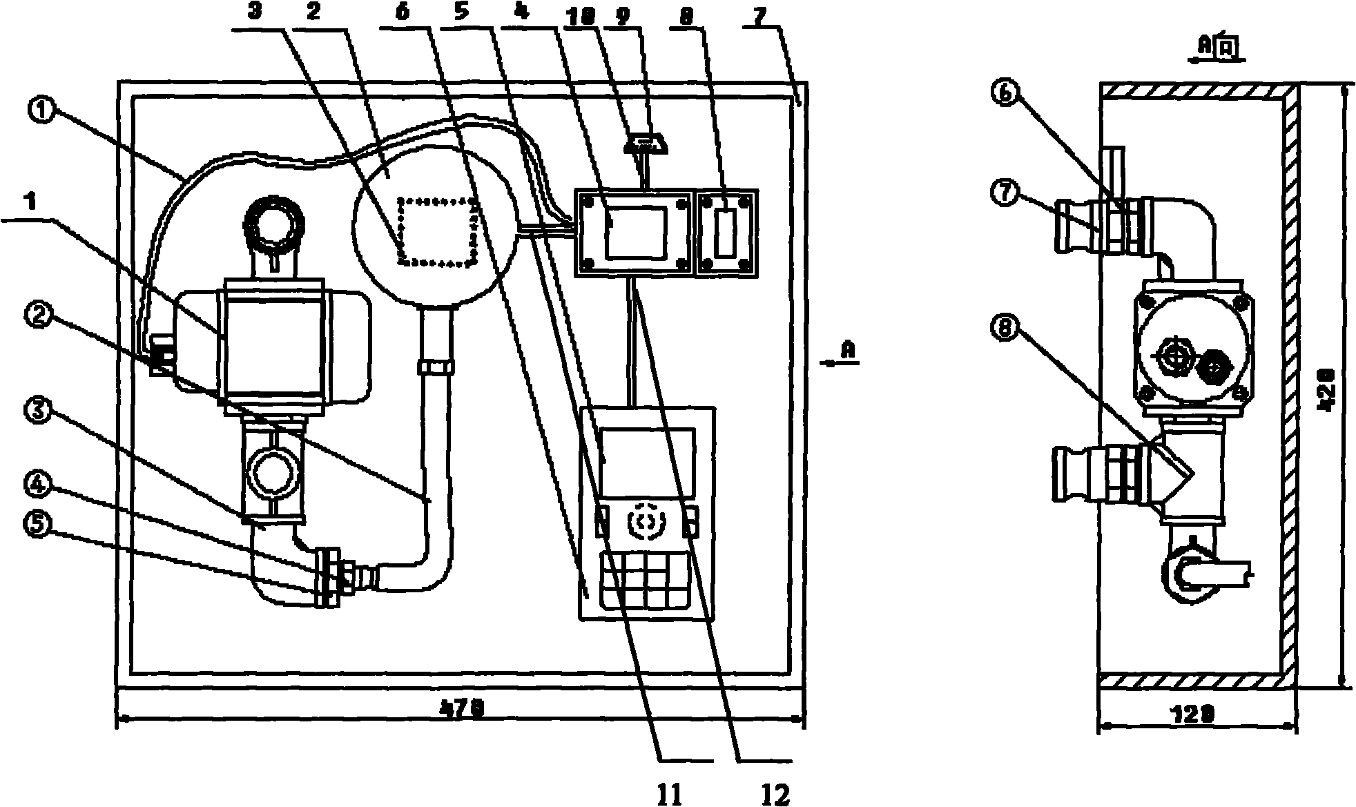
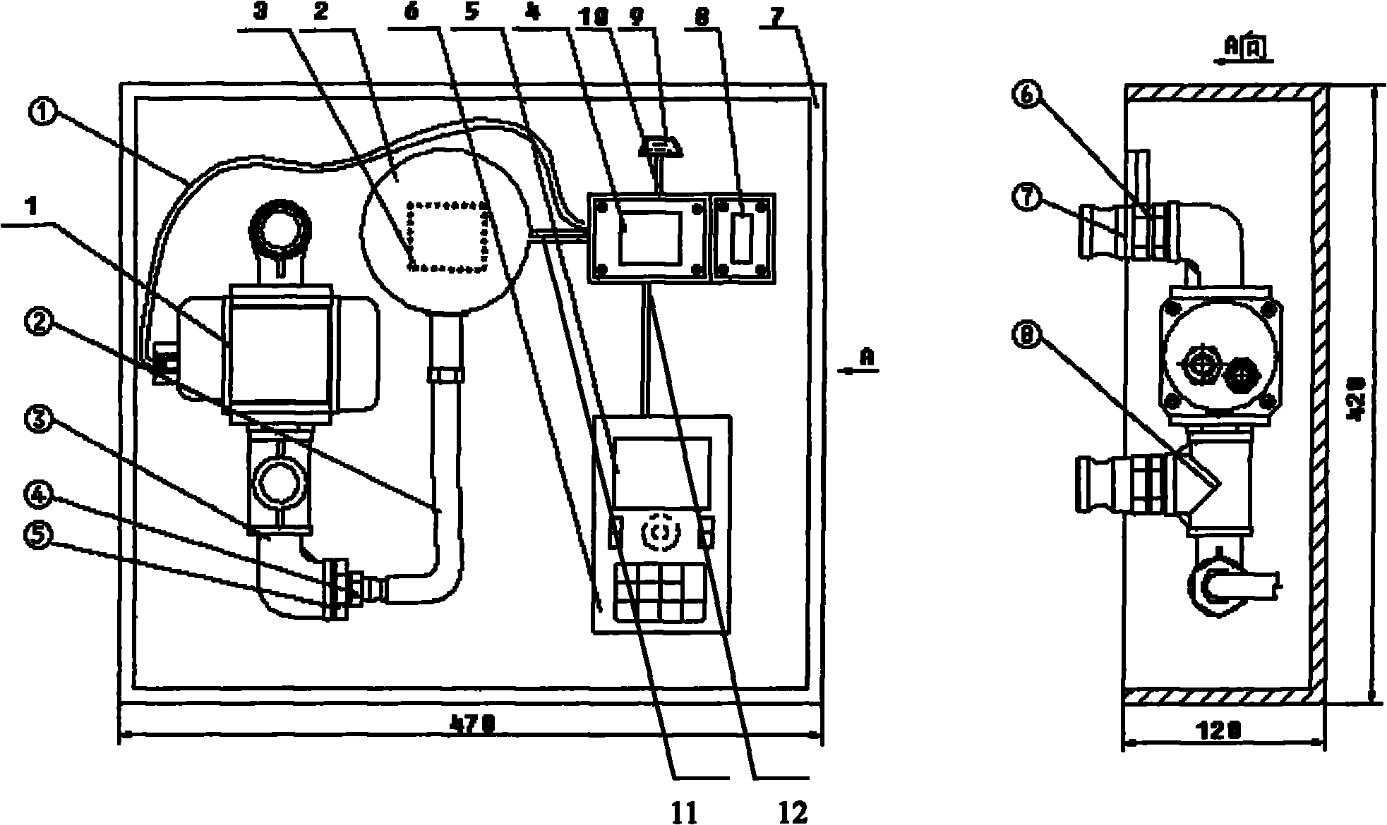
[0029] As shown in the figure, the implementation of the present invention includes: the gas path system consists of an air inlet (⑦), a pair of wires (⑥), an elbow, a flow sensor (1), a tee (8), an elbow (③), a bushing (⑤), pagoda connector (④), hose (②), pressure sensor (2), the circuit system consists of flow sensor (1), pressure sensor (2), power supply (3), single-chip processing module (4) , display screen (5), input keyboard (6), data memory (8), printer interface (9) and connecting cables (①, 10, 11, 12), the gas system and circuit system are integrated and installed in the equipment box (7) inside.

[0030] As shown in the figure, the connection description of each device is as follows:

[0031] 1. Air inlet (⑦), pair of wires (⑥), elbow, flow sensor (1), tee (8), elbow (③), bushing (⑤), pagoda joint (④), hose (②) and the gas system composed of the pressure sensor (2), the pipe joints use sealant to ensure that the gas does not leak under the pressure of 5000Pa.

[0...


PUM


Abstract

The invention relates to a method and instrument for detecting an oil gas recovery system of a gas station, in particular to an oil gas recovery detecting method and an intelligent detecting instrument, wherein the detecting method comprises the step of detecting the tightness, the liquid resistance and the gas liquid ratio of the oil gas recovery system of the gas station according to the programmed sequence by adopting a flow and pressure matching mode, and the detection data is automatically saved and can be printed on the spot or transmitted to a computer; and the intelligent detecting instrument comprises an anti-explosion circuit system and a closed gas path system, wherein the anti-explosion circuit system comprises a power supply source, a Roots flow sensor, a digital pressure sensor, a display screen, an input keyboard, a single chip microcomputer processing module, a data memory, a printer interface, a data transmission interface and the like, the closed gas path system comprises a flow sensor, a pressure sensor, a pipe fitting, a flexible pipe and a quick joint, and the circuit system and the gas path system are matched with a panel to be integrally installed in a box body. The detecting method of the invention is distinct, flexible, simple and convenient; and the detecting instrument of the invention has compact structure and perfect functions and can be carried, used, maintained and repaired simply and easily.

Description

technical field [0001] The invention belongs to the detection method and the equipment of the realization method of the oil gas recovery system of the gas station, and particularly relates to the programmed, standardized, automatic and intelligent detection of the airtightness, liquid resistance and gas-liquid ratio of the oil gas recovery system. Background technique [0002] With the rapid development of economy and society, the number of automobiles and gas stations in my country is increasing day by day. The pollution problem of gas stations has been widely valued by the society. The oil and gas spilled during vehicle refueling and oil transportation will damage the environment and waste resources. become an urgent problem to be solved. Oil and gas recovery transformation of gas stations is the general trend and is imperative. Oil and gas recovery at gas stations is divided into two stages: oil collection and oil delivery, which are called the first and second stages of ...

Claims


Application Information

Patent Timeline
Patent Type & Authority Applications(China)
IPC IPC(8): G01M99/00G01M3/32
Inventor 刘红旗刘江涛张健顾坚张枫吴哲刘登国黄平江
Owner 中机生产力促进中心有限公司
Why Eureka
Try Eureka