
Self-adaption voltage regulator based on optimized PSM modulation mode

A technology of self-adaptive voltage and modulation mode, applied in the direction of control/regulation system, regulation of electrical variables, instruments, etc., can solve the problems of complicated circuit implementation method, compensation loop oscillation phenomenon, time-consuming system error correction, etc., to achieve electromagnetic compatibility The effect of good characteristics, fast response speed and strong anti-interference ability

Inactive Publication Date: 2011-03-30
UNIV OF ELECTRONIC SCI & TECH OF CHINA
View PDF2 Cites 17 Cited by
  • Summary
  • Abstract
  • Description
  • Claims
  • Application Information

AI Technical Summary

Problems solved by technology

1) Mukti Barai and others used ADC, DPID, and DPWM to form a control loop to make an adaptive DC-DC converter (see the document "Dual-Mode Multiple-Band Digital Controller for High-Frepuency DC-DC Converter", Power Electronics, IEEE Transactions on Volume 24, Issue 3, March 2009 Page(s): 752-766), but this method requires digital loop compensation (and digital loop compensation usually needs to be modeled to obtain compensation parameters, and the modeled parameters Impossible to be very accurate, this will inevitably lead to more or less oscillation in the compensation loop; and eventually lead to output voltage instability); 2) Shidhartha Das et al. According to the operation of the load circuit (CPU or DSP) during the voltage regulation process The error rate is used to regulate the voltage, and the error correction mechanism is used to correct errors to achieve adaptive voltage regulation (see the document "Razor II: In Situ Error Detection and Correction for PVT and SER Tolerance", Solid-State Circuits, IEEE Journal of Volume 44 , Issue 1, Jan.2009Page(s): 32-48), but this method is complex to implement and time-consuming for system error correction
3) Dae Woon Kang et al. designed a fully digital adaptive Buck power converter that does not require PID (proportional, integral and differential) compensation based on a finite state machine (see the document "A High-Efficiency Fully Digital Synchronous Buck Converter Power Delivery System Based on a Finite-State Machine", Very Large Scale Integration (VLSI) Systems, IEEE Transactions on Volume 14, Issue 3, March 2006 Page(s): 229-240), but its circuit implementation is more advanced than the method described in the present invention for complex

Method used


Image

  • Self-adaption voltage regulator based on optimized PSM modulation mode
  • Self-adaption voltage regulator based on optimized PSM modulation mode
  • Self-adaption voltage regulator based on optimized PSM modulation mode

Examples


Embodiment Construction

[0024] specific implementation plan

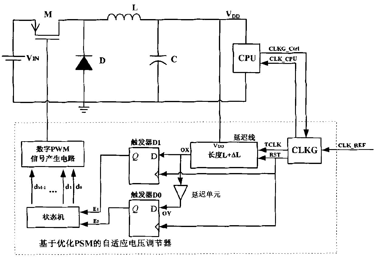
[0025] An adaptive voltage regulator based on an optimized PSM modulation scheme, such as figure 1As shown, it includes a clock signal generator CLKG, a delay line, two flip-flops D0 and D1, a state machine and a digital PWM signal generation circuit. The external clock signal source provides the reference clock signal CLK_REF for the clock signal generator CLKG; the clock signal generator CLKG generates three clock signals according to the control signal CLKG_Ctrl of the operating frequency requested by the external load processor: load processor clock signal CLK_CPU, delay line reset Signal RST and delay test signal TCLK; the delay line reset signal RST and delay test signal TCLK are N frequency division signals of the load processor clock signal CLK_CPU, N is an integer greater than or equal to 2, and the delay line reset signal RST rising edge ratio The rising edge of the delay test signal TCLK lags a clock cycle of the load processor...


PUM


Abstract

The invention relates to a self-adaption voltage regulator based on an optimized PSM modulation mode, belonging to the technical field of power electronics and being used for self-adaption on-line regulation on a power supply voltage of a load processor (CPU or DSP). In the self-adaption voltage regulator, a key path of the load processor is copied by adopting a delay line, an N frequency division signal of a working clock of the load processor is used as a delay test signal, and a trigger is used for detecting whether the transmission speed of the delay test signal reaches the requirement in the delay line. When the load processor is in a certain working frequency, if the VDD (Voltage Drain Drain) is overhigh, the delay test signal can pass through the delay line, a power switch of an external power inverter is trially shut off for reducing the VDD; and when the delay test signal can not pass through the delay line, optimized PSM modulation signals with different duty ratios are trially adopted for conducting the power switch of the external power inverter for improving the VDD, and finally, the load processor is ensured to work with minimum voltage under a given working clock frequency, thus the power consumption of the load processor is effectively reduced.

Description

technical field [0001] The invention belongs to the technical field of power electronics and is used for self-adaptive on-line adjustment of power supply voltage with digital control function for processor (CPU or DSP) load. Background technique [0002] In recent years, with the improvement of the integration level of integrated circuits, the power density of integrated circuits has become larger and larger. The power consumption of current processors can reach more than 100 watts, and the radiators are bulky and expensive. At the same time, the development speed of battery technology lags far behind the demand for electric energy of integrated circuits, which has become an important factor restricting the development of integrated circuits. [0003] Many complex electronic components, such as central processing units (CPUs) and digital signal processors (DSPs), can operate at different clock frequencies. In a digital circuit operating at high frequency, the switching powe...

Claims


Application Information

Patent Timeline
IPC IPC(8): G05F1/56
Inventor 罗萍李航标甄少伟张波李江昆贺雅娟
Owner UNIV OF ELECTRONIC SCI & TECH OF CHINA
Learn More