Clock synchronization method and system of master/salve clock equipment

A clock synchronization and master clock technology, applied in time division multiplexing systems, transmission systems, synchronization devices, etc., can solve problems such as time synchronization, network congestion, and increased operation and maintenance costs, so as to realize dynamic notification and improve flexibility sexual effect

Active Publication Date: 2011-03-30
ZTE CORP
View PDF2 Cites 17 Cited by
  • Summary
  • Abstract
  • Description
  • Claims
  • Application Information

AI Technical Summary

Problems solved by technology

Since the protocol has stipulated the multicast group, if there are multiple master clock devices in the network to multicast at the same time, it is necessary to physically isolate each master clock device and the slave clock devices it serves as a group during deployment. Otherwise, the slave clock device will receive multicast packets from multiple master clock devices, the time cannot be synchronized, and a large number of multicast packets on the network will easily cause network congestion
[0014] To sum up, the above two traditional methods lack flexibility in deployment, increase the cost of operation and maintenance, and also bring great difficulties to the implementation of the project

Method used


Image

  • Clock synchronization method and system of master/salve clock equipment
  • Clock synchronization method and system of master/salve clock equipment
  • Clock synchronization method and system of master/salve clock equipment

Examples


Embodiment 1

[0063] In this embodiment, a mobile communication BSS (Base Station System, base station subsystem) is taken as an example to introduce the PTP dynamic deployment solution of the present invention.

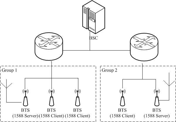
[0064] Such as figure 2 As shown, when the BTS (Base Station Transceiver, Base Station Transceiver) of multiple BSSs is connected to the BSC (Base Station Controller, Base Station Controller), some of the BTSs are connected to GPS as the master clock device, and other BTSs The base station provides time synchronization service.

[0065] The first step is to logically divide all BTSs into groups, and ensure that at least one BTS is connected to GPS as the main clock device in each group.

[0066] Wherein, devices among the divided logical groups do not overlap, that is, a master clock device or a slave clock device can only belong to one logical group, and cannot belong to multiple logical groups at the same time. In this example, if figure 2 Shown is divided into two groups, ...

Embodiment 2

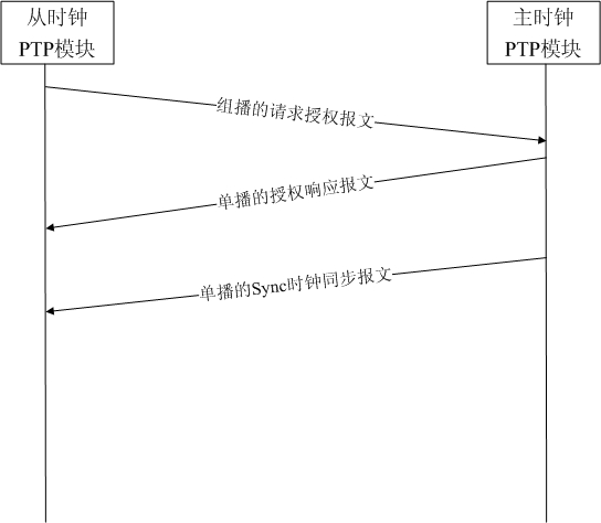
[0078] image 3 It shows the interactive signaling flow of the master-slave clock device implementing clock synchronization in the embodiment of the present invention, as shown in image 3 As shown, the specific description of the process is as follows:

[0079] Step 1, the slave clock device periodically sends a multicast request authorization PTP message, carries its own group number in the PTP message, and uses the reserved field of the PTP message header; at the same time, it also carries synchronization in the PTP message (Sync) Request authorization service information.

[0080] Step 2, after the master clock device receives the multicast request authorization PTP message from the slave clock device, it takes out the group number from the PTP message, and judges whether the slave clock device is in the same group as itself according to the group number, and if so, Then record the IP address of the slave clock device, and respond to the slave clock device with a unicast...

Embodiment 3

[0084] Figure 4 A schematic diagram of a synchronization process implemented by a slave clock device PTP module according to an embodiment of the present invention, as Figure 4 As shown, the process is described in detail as follows:

[0085] Step 1, the slave clock device regularly sends a multicast request authorization message;

[0086] Step 2, the master clock device judges whether the received authorization message belongs to the same group as itself, if yes, execute the next step 3, otherwise, return to step 1;

[0087] Step 3, recording the IP address of the master clock device;

[0088] Step 4, judge whether the clock synchronization service message is received, if yes, then perform the next step 5, otherwise, return to step 1;

[0089] Step 5, the slave clock device synchronizes the local clock according to the received clock synchronization service message.

[0090] Step 6: After the requested authorization service expires, the slave clock device re-sends a uni...


PUM


Abstract

The invention discloses clock synchronization method and system of master / salve clock equipment. The method comprises the steps of: when authorization is requested from the clock equipment, carrying the type of a request service and a logic group ID (Identity) allocated in advance in a sent multicast request authorization message; and after main clock equipment in the same logic group receives the request authorization message, sending unicast authorization response message to the slave clock equipment and sending a corresponding service message to the slave clock equipment according to the type of the request service. Compared with the prior art, the invention realizes the dynamic deployment of the main / slave clock equipment, realizes the dynamic notification of the IP (Internet Protocol) addresses of the master / slave clock equipment through PTP (Peer to Peer) protocol interaction, supports the grouping of the master / slave clock equipment and improves the flexibility of a network element architecture design scheme.

Description

technical field [0001] The invention relates to the technical field of clock synchronization, in particular to a clock synchronization method and system for master-slave clock devices. Background technique [0002] Mobile networks have strict requirements on high-precision clock synchronization. The purpose of clock synchronization is to synchronize the clocks of each node in the network to the same reference. Wireless systems based on FDD (Frequency Division Duplex, Frequency Division Duplex) such as UMTS (Universal Mobile Telecommunications System, Universal Mobile Communication System) require frequency synchronization between nodes, while wireless systems based on TDD (Time Division Duplex, Time Division Duplex) Systems such as TD-SCDMA (Time Division-Synchronous Code Division Multiple Access, Time Division Synchronous Code Division Multiple Access) / CDMA2000, etc. require clock frequency and phase synchronization. [0003] At present, GPS (Global Positioning System, Glo...

Claims


Application Information

Patent Timeline
Patent Type & Authority Applications(China)
IPC IPC(8): H04L7/00H04L29/06
CPCH04J3/0667
Inventor 常伟廖俊锋李福军
Owner ZTE CORP
Why Eureka
Try Eureka