
Microelectrode propelling device and method

A propulsion device and micro-electrode technology, applied in electrodes, internal electrodes, medical science, etc., can solve the problems of non-reusable, incapable of skull connection, large contact area, etc., to reduce the difficulty of design and manufacture, and facilitate processing and experimental assembly , Guarantee the effect of connection and positioning

Inactive Publication Date: 2011-04-06
NANJING UNIV OF AERONAUTICS & ASTRONAUTICS
View PDF3 Cites 7 Cited by
  • Summary
  • Abstract
  • Description
  • Claims
  • Application Information

AI Technical Summary

Problems solved by technology

The disadvantages are: (1) The contact area with the skull is relatively large, which is not suitable for animals with special skull structures such as geckos; (2) The implantation site of the microelectrode is fixed, and the area where the microelectrode can be implanted is relatively small; (3) The slider is one-time use and cannot be reused; (4) Compared with animals such as big geckos, the structure is relatively large, which is not conducive to the free movement of animals
[0009] Since the above microelectrode thrusters are mainly aimed at animals such as rats and cats, they are used in the stimulation and recording experiments of large geckos. There are many problems, such as the inability to connect with the skull of large geckos, the area where microelectrodes can be implanted is relatively small, etc. Wait

Method used


Image

  • Microelectrode propelling device and method
  • Microelectrode propelling device and method
  • Microelectrode propelling device and method

Examples


Embodiment Construction

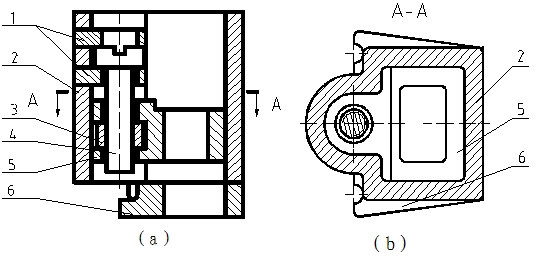
[0032] figure 1 is a schematic diagram of the microelectrode pusher. As shown in the figure, two gaskets 1 are used to limit the up and down movement of the screw 4, so the screw 4 can only rotate in situ, and the nut 3 is tightly connected with the slider 5. When the screw 4 is turned, the slider 5 is limited by the casing 2 to rotate, so the slider 5 can only move up and down along the screw 4 with the nut 3 . After the microelectrode is fixed on the hole array plate bonded to the slider 5, the microelectrode will also move up and down along with the slider 5.

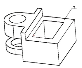
[0033] figure 2 is a schematic diagram of the slider. The area marked with in the figure is the stepped groove, which is used to bond the hole array plate.

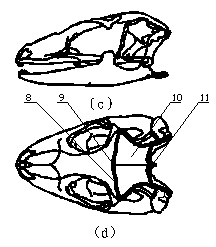
[0034] image 3 is a schematic diagram of the localization of the gecko head position and the experimental area. The area available for the experiment is the parietal bone between the bregma and bregma, that is, the area marked with a thick line, with a ...


PUM

PropertyMeasurementUnit
Thicknessaaaaaaaaaa

Abstract

The invention discloses a microelectrode propelling device and a microelectrode propelling method. The device comprises a gasket, a box body, a nut, screws, a slide block and a bottom plate. The propelling method comprises the following steps that: the periphery of the bottom plate is arranged into a step shape, the bottom plate is positioned on a skull by positioning screws through two semicircular holes serving as positioning reference on the bottom plate and positioning holes at corresponding positions on the skull, and the bottom plate and the skull are bonded and fixed through dental cement; the bottom plate is connected with the box body through concavely and convexly matched grooves; the slide block is arranged inside a slideway of the box body, an array plate is arranged on a stepped groove of the slide block so as to fix a microelectrode, the position of a hole on the array plate is the position of intersecting axles of a sagittal plane and a coronal plane at a brain region-specified space encoding position, a horizontal position of the array plate is a propelling surface of a propeller, and the propeller performs electrical brain stimulation and encephalographic record on the whole brain region. The propelling device has the characteristics that: the operation is simple and the structure is light, and the device is suitable for labs for researching animal brain regions.

Description

technical field [0001] The invention relates to a manual microelectrode propeller, which is used for feeding microelectrodes in the brain of a gecko that can move freely in a waking state. Background technique [0002] How the information of external things is encoded and transmitted in the brain has always been an important research topic in brain science. The encoding of neural information is a fundamental problem of the nervous system. The information of things is coded by neuron clusters. The use of cluster coding is conducive to the stability and accuracy of neural information expression, and through combination, more different representations than the number of neurons can be generated, thereby improving the expressive ability of the nervous system. It is a promising topic to study the high-order characteristics of expressing the interrelationships of multiple neurons in a cluster and then develop other more effective encoding modes. [0003] A series of studies, suc...

Claims


Application Information

Patent Timeline
IPC IPC(8): A61B5/0478A61N1/05
Inventor 戴振东刘振东王文波蔡雷
Owner NANJING UNIV OF AERONAUTICS & ASTRONAUTICS
Learn More