Automatic welding device of circular weld beads

An automatic welding and welding bead technology, applied in auxiliary devices, welding equipment, auxiliary welding equipment, etc., can solve the problems of large influence on welding quality and welding consistency, lack of effective guarantee, and low labor intensity. Improve welding quality and welding consistency, simple structure, good weld bead quality

Inactive Publication Date: 2011-04-06
GREAT WALL MOTOR CO LTD
View PDF9 Cites 3 Cited by
  • Summary
  • Abstract
  • Description
  • Claims
  • Application Information

AI Technical Summary

Problems solved by technology

Manual welding means that the operator holds the welding torch and the welding cap, and welds the straight line and arc weld bead of the workpiece under the observation of the eyes. The disadvantage is that the labor intensity of the workers is high, the production efficiency is low, and the welding quality and welding consistency are affected by the operation. The welding skills, physical condition and other factors of the operator are greatly affected and cannot be effectively guaranteed; robot welding controls the welding equipment through computer programming, so that the equipment can automatically weld various welds, with high welding quality, fast welding speed, The advantage of low labor intensity is that the investment cost is too high. An ordinary robot welding equipment needs to invest about 100,000 yuan, and the operator must master professional programming skills.
[0003] In the actual production process, it is often necessary to weld two coaxial circular or cylindrical parts together, for example, in figure 1 The workpiece 2 that needs to be welded is a step pin and a gasket, and there is a circular weld bead between them. Obviously, it is difficult to use manual welding, and the robot welding method is not suitable for this small workpiece

Method used


Image

  • Automatic welding device of circular weld beads
  • Automatic welding device of circular weld beads
  • Automatic welding device of circular weld beads

Examples


Embodiment Construction

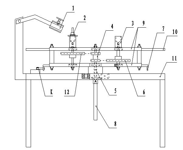
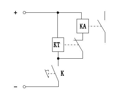
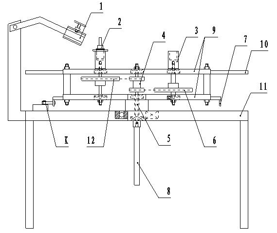
[0016] see figure 1 , figure 2 , Assembly of the present invention: the wire feeding motor of the carbon dioxide shielded welding machine is connected with the vertical shaft 5 through the transmission shaft 8 . Fasten the welding torch of the welding machine on the welding torch bracket 1, and adjust the relative position of the welding torch and the workpiece positioning seat 3 to ensure the angle and distance of welding. Unplug the circuit control plug of the welding torch, and plug in the control circuit of the circular bead automatic welding device. Adjust the delay time of the time relay KT through test welding. The workpiece speed can be controlled by adjusting the current of the welding machine and the size of the proportioning sprocket.

[0017] Welding of the workpiece: Rotate the welding platform 9 out of the welding position by 90 degrees clockwise / counterclockwise, install the workpiece at a position that does not hinder the upper part, and place the workpiece...


PUM


Abstract

The invention relates to an automatic welding device of circular weld beads, which is used for improving the welding quality and the welding efficiency of the circular weld beads and is characterized by comprising a machine frame, a vertical rotating shaft, a welding platform, a workpiece positioning seat, a carbon-dioxide protection welder and a control circuit, wherein the lower end of the vertical rotating shaft is rotatably connected with the machine frame, the upper end of the vertical rotating shaft is rotatably connected with the welding platform, the workpiece positioning seat is positioned on the welding platform and is rotatably connected with the welding platform, a welding torch of the carbon-dioxide protection welder is fixed on the machine frame through a welding torch support frame, and a wire feeding motor of the carbon-dioxide protection welder forms the driving relationship with the workpiece positioning seat sequentially through a transmission shaft, the vertical rotating shaft and chain wheels. The automatic welding device has simple structure, low cost, high welding efficiency and good weld bead quality, is convenient to operate and is particularly suitable for welding the circular weld beads on small members.

Description

technical field [0001] The invention relates to a carbon dioxide shielded welding equipment, which can automatically and efficiently complete the welding of a circular bead, and belongs to the field of welding technology. Background technique [0002] At present, two welding methods are usually used in the machinery manufacturing industry: manual welding and robotic welding. Manual welding means that the operator holds the welding torch and the welding cap, and welds the straight line and arc weld bead of the workpiece under the observation of the eyes. The disadvantage is that the labor intensity of the workers is high, the production efficiency is low, and the welding quality and welding consistency are affected by the operation. The welding skills, physical condition and other factors of the operator are greatly affected and cannot be effectively guaranteed; robot welding controls the welding equipment through computer programming, so that the equipment can automatically ...

Claims


Application Information

Patent Timeline
Patent Type & Authority Applications(China)
IPC IPC(8): B23K37/00
Inventor 李建国苏二虎王洋
Owner GREAT WALL MOTOR CO LTD
Why Eureka
Try Eureka