Device and method for separating residue from catalytic cracking oil slurry

A technology for catalytic cracking of oil slurry and residues, which is applied in the petrochemical field and can solve the problems of filter blockage, easy blockage of the filter, and inability to achieve complete separation of liquid and solid.

Active Publication Date: 2011-04-06
SHANGHAI LANKE PETROCHEM ENG & TECH
View PDF8 Cites 39 Cited by
  • Summary
  • Abstract
  • Description
  • Claims
  • Application Information

AI Technical Summary

Problems solved by technology

Although this patent can thoroughly purify catalytic cracking oil slurry, the process conditions are harsh and the cost is too high, so it is not easy to promote industrialization
[0006] The second is to introduce an organic solvent (water) or other additives into the oil slurry to transfer the residual catalyst particles in the oil slurry to the extraction solvent through extraction and demulsification. The disadvantage of this method is that not only A large amount of solvent is consumed, and the complete separation of liquid and solid cannot be achieved
[0008] 1. The filter is easy to block. After investigation, the technicians of the chemical refinery who currently adopt the filtration separation method for catalyst recovery and separation generally report that the blockage of the filter is very serious, which often leads to downtime for maintenance, which is time-consuming and laborious. The phenomenon of filter blockage leads to Manufacturers at home and abroad have basically given up using this method for catalytic cracking oil-s

Method used


Image

  • Device and method for separating residue from catalytic cracking oil slurry
  • Device and method for separating residue from catalytic cracking oil slurry
  • Device and method for separating residue from catalytic cracking oil slurry

Examples


Embodiment Construction

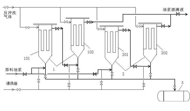
[0036] Such as figure 1 As shown, a device for separating residues from catalytic cracking oil slurry using the process method of the present invention includes two sets of filter sets. The first filter set 1 is composed of a pre-filter 101 and a fine filter 102 connected in series. The top of filter 101 is provided with a pre-filtered oil outlet, and this pre-filtered oil outlet is connected to the bottom of fine filter 102, and the second filter group 2 is made up of pre-filter 201 and fine filter 202 connected in series, pre-filter The top of 201 is provided with a pre-filtered oil outlet, and the pre-filtered oil outlet is connected to the bottom of fine filter 202 . Filter cake tank 3 is arranged on the bottom of prefilter 101,201 and fine filter 102,202, is used to hold the filter cake after stripping and the cleaning oil after cleaning; There is a raw material oil slurry inlet and a cleaning oil inlet, and the bottom end of the fine filter 102, 202 is provided with a ...


PUM


Abstract

The patent discloses a device for separating residue from catalytic cracking oil slurry, which comprises at least two filter sets and a filter cake tank, wherein the at least two filter sets are formed by connecting pre-filters and fine filters; the filter cake tank is arranged between the bottoms of the pre-filters and the fine filters for accommodating a peeled filter cake and washed washing oil; the bottom of each pre-filter is connected with a raw material oil slurry inlet and a washing oil inlet, and the bottom of each fine filter is connected and provided with a washing oil inlet for washing the filter core of the filter; an oil slurry filtrate outlet is formed on the top of each fine filter; and backwash air inlets are formed on the tops of both the pre-filters and the fine filters. Meanwhile, the patent also discloses a method using the device. The residual catalyst content of the oil slurry filtrate processed by the device in the patent is less than 0.01 percent, and filtrate content is less than 0.02 percent.

Description

technical field [0001] The invention relates to the field of petrochemical industry, in particular to a device and method for improving the quality of catalytic cracking oil slurry by filtering and removing asphaltenes and residual catalyst particles in catalytic cracking oil slurry. Background technique [0002] Catalytic cracking is the most important heavy oil lightening process in the oil refining industry. The catalytic cracking oil slurry contains a large amount of aromatics and naphthenes and some aromatic components with low condensation degree. Components can be used as raw materials for hydrocracking to produce high-quality light hydrocarbon components; in addition, due to heavy components and high aromatic content, catalytic cracking oil slurry has high density, high viscosity, and high solubility and compatibility with polymer materials. Compatibility etc. However, due to the existence of asphaltenes and catalyst particle residues in ordinary catalytic cracking ...

Claims


Application Information

Patent Timeline
IPC IPC(8): C10G31/09
Inventor 马洪玺张文军李明代辉
Owner SHANGHAI LANKE PETROCHEM ENG & TECH
Why Eureka
Try Eureka