LED (Light Emitting Diode) integrated structure with cooler

A technology of cooling device and refrigeration device, which is applied to components of lighting devices, cooling/heating devices of lighting devices, lighting devices, etc., and can solve problems such as low yield rate of LED chips, poor cooling effect of cooling devices, and short service life. , to save cost and facilitate layout design

Inactive Publication Date: 2011-04-06
杨东佐
View PDF10 Cites 25 Cited by
  • Summary
  • Abstract
  • Description
  • Claims
  • Application Information

AI Technical Summary

Problems solved by technology

[0015] In order to solve the poor heat dissipation caused by excessive thermal resistance in the middle link of the existing LED integrated structure, short life, low luminous efficiency, low yield rate caused by low reliability of chip electrical interconnection, and LEDs packaged by COB technology The optical effect of the chip integrated structure is not good, and the cooling effect of the cooling device is not good. The technical problem to be solved by the present invention is to provide an intermediate link with small thermal resistance, good heat dissipation, direct electrical connection between the chip and the conductive layer of the layout circuit, and no Reflow soldering or wave soldering is required, resin or silica gel can be used for packaging colloid, the positional relationship between the lens and the chip is accurate, it has high luminous flux, simple structure, simple assembly, good heat dissipation effect, good optical effect, and good heat dissipation of LED chip with cooling LED integrated structure of the device

Method used


Image

  • LED (Light Emitting Diode) integrated structure with cooler
  • LED (Light Emitting Diode) integrated structure with cooler
  • LED (Light Emitting Diode) integrated structure with cooler

Examples


Embodiment 1

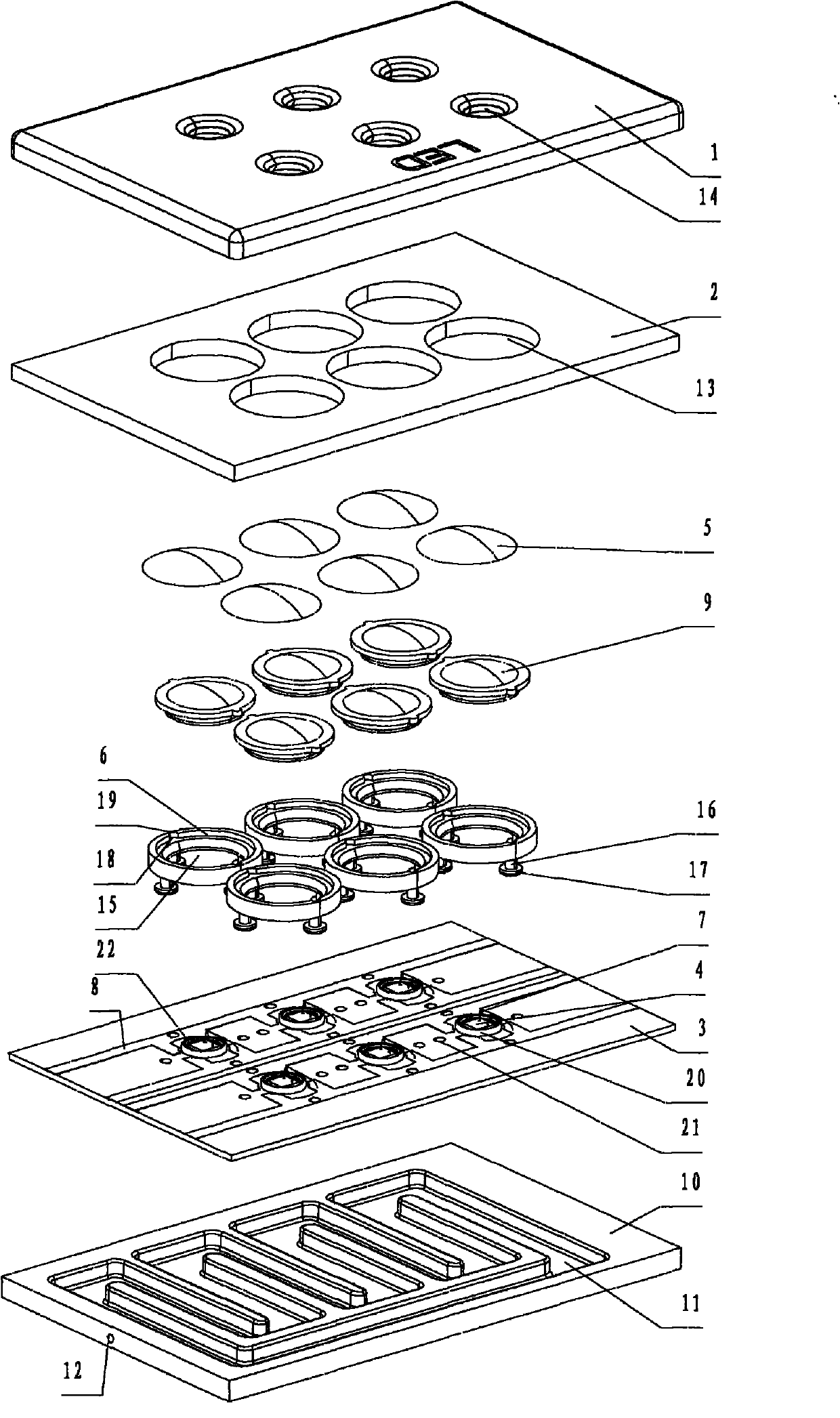
[0079] Such as figure 1 As shown, an LED integrated structure with a cooling device includes a cover plate 1, a reflector plate 2, a heat dissipation substrate 3, an LED chip 4, a lens 5, a lens positioning ring 6, and a gold wire 7 electrically connected to an electrode of the LED chip 4 and the layout circuit conductive layer 8 electrically connected to the gold wire 7 , and the encapsulant 9 used to encapsulate the LED chip 4 and the gold wire 7 . The cooling device includes a flow channel plate 10 arranged on the side of the heat dissipation substrate 3 away from the LED chip 4, a groove 11 is provided on the flow channel plate 10, and a storage cooling is formed between the groove 11 on the flow channel plate 10 and the heat dissipation substrate 3. The water cooling channel and the device for driving the cooling water flow (not shown), the device for driving the cooling water flow is a water pump. A cooling water inlet 12 and a cooling water outlet (not shown) communica...

Embodiment 2

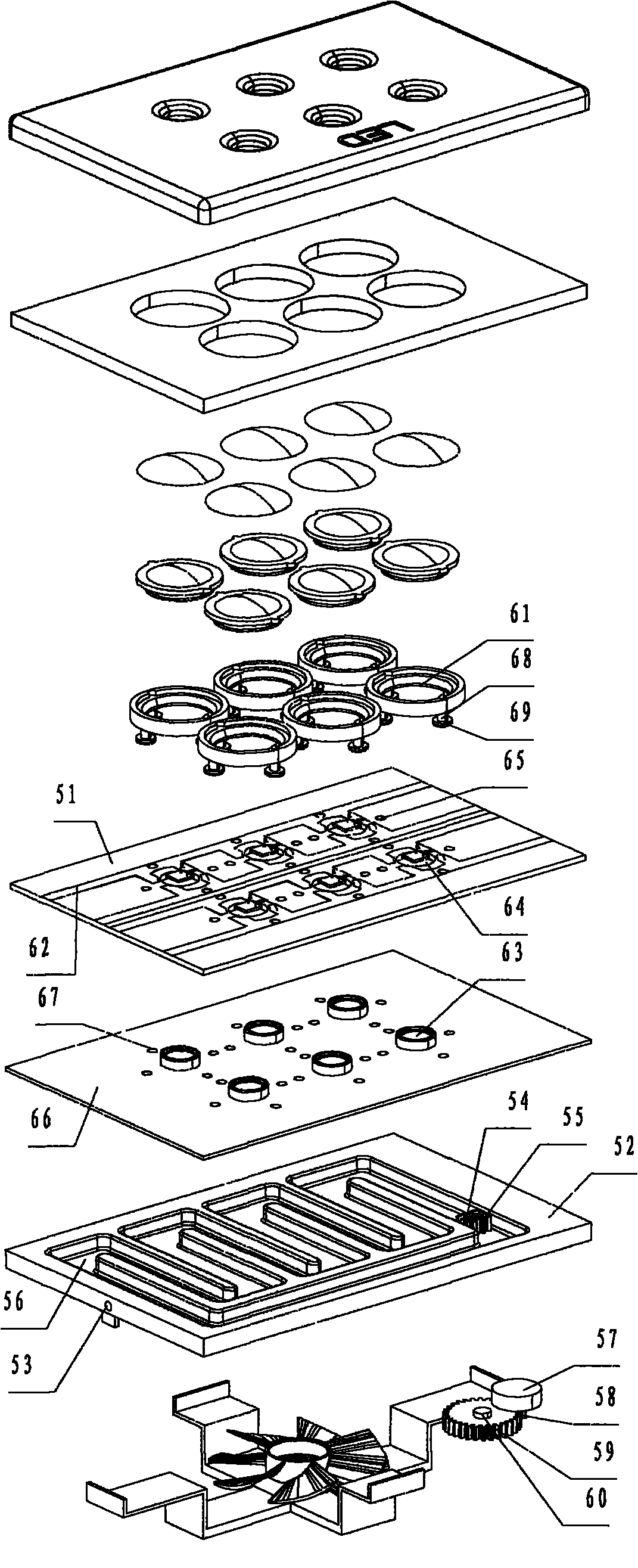
[0084] Such as figure 2As shown, the difference from Embodiment 1 is that an LED integrated structure with a cooling device also includes a PCB board 51 . The flow channel plate 52 is only provided with a cooling medium inlet 53 communicating with the cooling flow channel. The groove 56 on the flow channel plate 52 and the heat dissipation substrate 66 form a closed circulation cooling flow channel, and the cooling medium circulates in the cooling flow channel. The device for driving cooling medium flow includes two first gears 54 and second gears 55 that are engaged with each other installed at the bottom of the groove 56, and are arranged on the side away from the groove 56 to drive the first gear 54 and the second gear 55 to rotate. Motor 57, gear 58 coaxially installed with driving motor 57, gear 59 meshed with gear 58, and magnet 60 fixed with gear 59. The first gear 54 rotates synchronously with the magnet through the magnetic force between the magnet and the magnet. ...

Embodiment 3

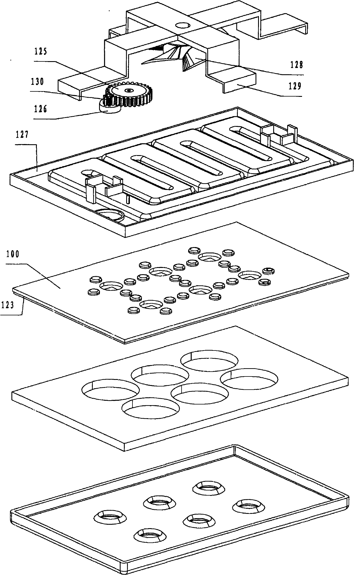
[0088] Such as image 3 As shown, the difference from Embodiment 2 is that the device for driving the cooling medium flow includes two intermeshing first gears (not shown) and second gears (not shown) installed at the bottom of the groove (not shown) 1. The drive motor 126 that is arranged on the side away from the groove to drive the first gear and the second gear to rotate, the gear 130 coaxially installed with the drive motor 126, and the gear 125 meshed with the gear 130 are installed on the channel plate 127 away from the groove The fan 128 on one side of the slot is fixed on the runner plate 127 through a bracket 129 . The first gear is coaxially fixed with the gear 125 and its fixed axis passes through the flow channel plate 127 . The gear shaft of the first gear and the gear shaft of the second gear are liquid-tightly sealed with the bottom of the groove.

[0089] Such as Figure 4 , Figure 5 As shown, the plastic lens positioning ring 101 is connected as a whole ...


PUM


Abstract

The invention relates to an LED (light emitting diode) integrated structure with a cooler. A plastic member is fixed with a heat radiation base plate through a fixed post and a stopping part, and an LED chip is directly fixed on the heat radiation base plate with a die bond process and is arranged in a corresponding first through hole; a layout circuit conducting layer extends into a part between the side wall of the first through hole and the LED chip, and a conducting wire and the LED chip are arranged in the first through hole; the cooler comprises a flow passage casing, a cooling flow passage and a cooling medium flowing driving device, wherein the flow passage casing is arranged at one side of the heat radiation base plate in deviation from the LED chip, and the cooling flow passage is used for accommodating cooling media and is formed between the flow passage casing and the heat radiation base plate; the back side of the LED chip is completely covered by the cooling flow passage, and the fixed post and the heat radiation base plate are sealed with gas or liquid; and one side of the heat radiation base plate in deviation from the LED chip is in direct contact with the cooling media. The LED integrated structure has the advantage of reducing the heat resistance of intermediate links to the maximum degree and achieving a good heat radiating effect, and the cooler has high heat exchange speed and good cooling effect.

Description

technical field [0001] The invention relates to an LED integrated structure with a cooling device for lighting, backlight module, TV, LED dot matrix display screen, projection equipment, etc., especially relates to a high-power LED integrated structure cooling device . Background technique [0002] LED light sources, especially high-power LED light sources, concentrate heat when emitting light. If the heat generated by the LED chip is not dissipated in time, the temperature of the LED light source will be too high, which will lead to reduced light efficiency and short life of the LED. The rapid and effective dissipation of the heat generated by LED chips when they emit light has become a bottleneck for the popularization and application of LED light sources. How to improve the light efficiency of the LED light source and how to improve the heat dissipation performance of the LED light source so as to prolong the service life are important technical problems in the industry ...

Claims


Application Information

Patent Timeline
Patent Type & Authority Applications(China)
IPC IPC(8): H01L25/13H01L33/48H01L33/64
CPCF21V17/06F21V29/2293F21Y2105/001F21V29/02F21Y2103/003H01L25/0753H01L33/642F21V5/007H01L2224/48227F21Y2113/007H01L2224/48091H01L33/58F21Y2101/02F21V29/677F21V29/83F21Y2103/10F21Y2105/10F21Y2113/17F21Y2115/10H01L2924/01322H01L2924/00014H01L2924/00
Inventor 杨东佐
Owner 杨东佐
Why Eureka
Try Eureka