Line cavity laser with super-narrow line width based on parallel feedback

An ultra-narrow linewidth and laser technology, applied in the field of communication, can solve the problems of high price, increasing the length of the para-erbium fiber, difficulty in ultra-narrow linewidth, etc., and achieve the effects of low cost, light weight and small volume

Inactive Publication Date: 2011-04-06
PEKING UNIV +1
View PDF5 Cites 15 Cited by
  • Summary
  • Abstract
  • Description
  • Claims
  • Application Information

AI Technical Summary

Problems solved by technology

However, further compression of the linewidth by this method requires a substantial increase in the length of the erbium-based fiber, making it diff

Method used


Image

  • Line cavity laser with super-narrow line width based on parallel feedback
  • Line cavity laser with super-narrow line width based on parallel feedback
  • Line cavity laser with super-narrow line width based on parallel feedback

Examples


Embodiment Construction

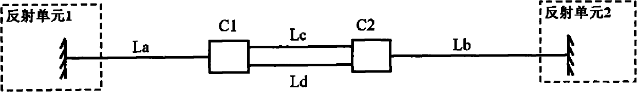
[0032] Before describing the embodiment of the ultra-narrow linewidth line cavity laser based on parallel feedback according to the present invention, a brief description of the term "parallel feedback loop" is given first.

[0033] In the present invention, the term "parallel feedback loop" refers to a feedback loop in which the positive feedback loop in the fiber laser is multi-path parallel. Utilizing parallel feedback loops, through the coherent superposition of light between different loops, the spectral characteristics of the final output laser can be improved.

[0034] figure 1 A basic parallel-feedback fiber cavity laser resonator structure is shown. Two couplers C1 and C2 are used in the resonator to build a Mach-Zehnder (MZ) structure. In this resonant cavity structure, there are four different closed resonant circuits. The superscript "+" indicates that the light propagates to the right, and the superscript "-" indicates that the light propagates to the left. The ...


PUM

PropertyMeasurementUnit
Diameteraaaaaaaaaa
Lengthaaaaaaaaaa
Lengthaaaaaaaaaa

Abstract

The invention provides a line cavity laser with super-narrow line width based on parallel feedback, which comprises a DFB (Distributed Feedback) laser, a 90:10 coupler, a reflection unit, multiple sections of single mode optical fibers and multiple mold optical fibers, wherein the DFB laser and the 90:10 coupler as well as the 90:10 coupler and the reflection unit are respectively coupled through an optical fiber structure composed of the single mode optical fibers and the multiple mold optical fibers.

Description

technical field [0001] The invention relates to the technical field of communication, and more specifically, to an ultra-narrow linewidth line cavity laser based on parallel feedback. Background technique [0002] A laser is a device that emits laser light, and its application has spread throughout many fields of science and technology, economy, military and social development. Fiber lasers use rare-earth-doped fiber as the gain medium. The pump light forms a high power density in the fiber core, causing the particle beam inversion of the energy level of the doped particles. When an appropriate positive feedback loop is added, the laser output is generated. Fiber laser is a new technology in the laser field. Compared with other dielectric lasers, it has the advantages of long gain region, compact structure, high energy density, strong anti-electromagnetic interference, small temperature expansion coefficient, and no need for additional heat dissipation devices. [0003] Las...

Claims


Application Information

Patent Timeline
IPC IPC(8): H01S5/12H01S5/06H01S5/026
Inventor 王子南王大量王翠云余晓琦朱立新蒋云李正斌
Owner PEKING UNIV
Why Eureka
Try Eureka