Great-power wind-power integration convertor suitable for cage asynchronous generator

An asynchronous generator, high-power technology, applied in the direction of controlling the generator through the change of the magnetic field, wind power generation, reactive power adjustment/elimination/compensation, etc., can solve the problem of the performance and life of the permanent magnet synchronous generator Differences, magnetic reduction of magnetic steel and other problems, to achieve the effect of enhancing stability and adaptability, high power level, and reducing grid-connected current

Inactive Publication Date: 2011-04-06
BAODING TIANWEI GRP CO LTD
View PDF2 Cites 11 Cited by
  • Summary
  • Abstract
  • Description
  • Claims
  • Application Information

AI Technical Summary

Problems solved by technology

Although, in recent years, with the continuous improvement of the performance of permanent magnet materials and the decline of prices, the price of permanent magnet synchronous motors has been greatly reduced and has gradually become accepted by the public, but due to the limitations of permanent magnet materials themselves; especially, in Under high temperature, vibration and other conditions, the magnetic properties of permanent magnets will deteriorate, and there is a danger of loss of magnetism; the difference in rare earth materials or production processes will also cause great differences in the magnetic properties of permanent magnets. Generator performance and longevity are detrimental
The problem of life is an important reason that limits its application in the field of wind power, because the current design life of wind turbines is basically 20 years, and the current use of permanent magnet motors shows that the magnetism of the magnets will decrease after a few years.

Method used


Image

  • Great-power wind-power integration convertor suitable for cage asynchronous generator
  • Great-power wind-power integration convertor suitable for cage asynchronous generator
  • Great-power wind-power integration convertor suitable for cage asynchronous generator

Examples


Embodiment Construction

[0028] The present invention will be further described through the embodiments below in conjunction with the accompanying drawings.

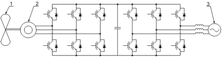
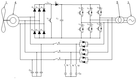
[0029] Refer to attached figure 2 , In the embodiment, the present invention is located between the megawatt wind turbine 1 , the cage-type asynchronous generator 4 , the grid-connected transformer 5 , and the grid 3 . The invention includes: rectifier unit, step-up chopper unit, inverter unit, motor soft start excitation unit C f1 (also has grid-side filtering function), grid-side three-phase reactive power compensation switching capacitor unit C f2 . Wind turbine 1 and cage-type asynchronous generator 4 are connected to the rectifier unit, the rectifier unit is connected to the boost chopper unit, the boost chopper unit is connected to the inverter unit, and the inverter unit is connected to the motor soft start excitation unit and grid-side three-phase reactive power compensation unit, where the motor soft start excitation unit C f1 and ...


PUM


Abstract

The invention relates to a great-power wind-power integration convertor suitable for a cage asynchronous generator, belonging to the technical field of new energy of wind and power. The invention adopts the technical scheme that a rectifying unit comprises at least one three-phase uncontrolled diode rectifier unit or a plurality of three-phase uncontrolled diode rectifier units connected in parallel, a boost chopper unit comprises at least one boost chopper unit or a plurality of boost chopper units connected in parallel, an inverter unit comprises at least one three-phase full-control inverter unit or a plurality of three-phase full-control inverter units connected in parallel, and a motor soft-start excitation unit comprises at least one three-phase soft-start excitation unit or a plurality of three-phase soft-start excitation units connected in parallel. By applying the low-cost cage asynchronous generator to wind-powered generation, the whole unit cost is greatly decreased, the control structure is simplified, and the stability and the suitability of the unit operation are enhanced.

Description

Technical field: [0001] The invention relates to a high-power wind power grid-connected converter suitable for a cage-type asynchronous generator, in particular to a megawatt-level high-power wind power grid-connected converter for a cage-type asynchronous generator, and belongs to the technical field of wind power new energy. Background technique: [0002] In recent years, the development of human society has entered a new period of rapid development, and the trend of global economic integration has become increasingly obvious. The three pillar industries of information, new energy and new materials have become an important cornerstone for mankind to move towards a new civilization in the 21st century, and the new energy industry plays a vital role in the rapid and sustainable development of the economy. Wind power technology is a relatively mature new energy technology with the most large-scale development conditions and commercial development prospects. It has the advanta...

Claims


Application Information

Patent Timeline
Patent Type & Authority Applications(China)
IPC IPC(8): H02M5/44H02J3/38H02P9/14H02J3/18
CPCY02E40/30Y02E10/763Y02A30/60Y02E10/76
Inventor 鲁志平王东刘广东赵双喜冯红岩申晓东
Owner BAODING TIANWEI GRP CO LTD
Why Eureka
Try Eureka