
Reset circuit

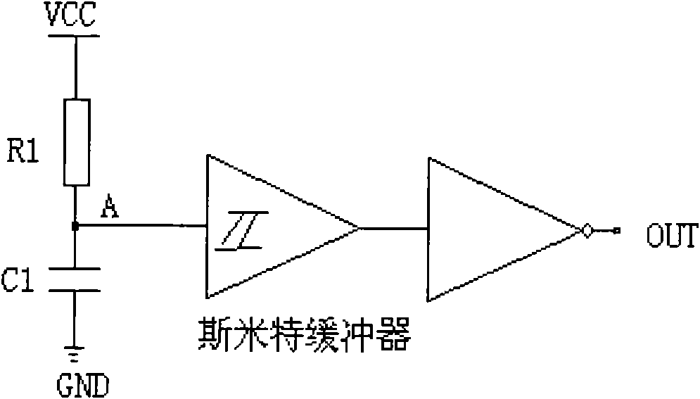
A technology for resetting circuits and circuits, which is applied in electrical components, electronic switches, pulse technology, etc., and can solve problems such as large operating current and complex circuits.

Active Publication Date: 2012-10-03
SUZHOU HUAXIN MICROELECTRONICS
View PDF4 Cites 0 Cited by
  • Summary
  • Abstract
  • Description
  • Claims
  • Application Information

AI Technical Summary

Problems solved by technology

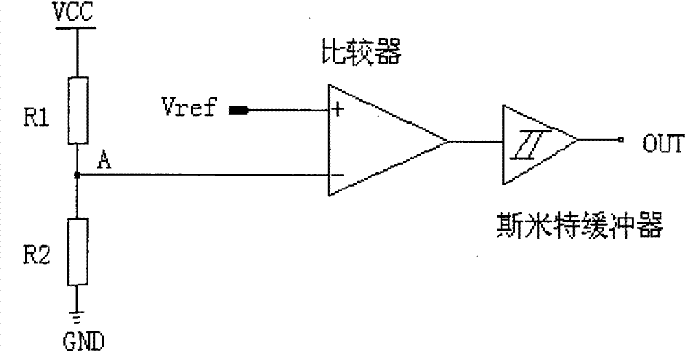
But the circuit is more complex
For example, Vref needs to be stable, a reference voltage circuit is needed, the comparator needs a current mirror to provide current, and the operating current is relatively large. Considering cost reduction and power consumption, it is not a good solution.

Method used


Image

  • Reset circuit
  • Reset circuit
  • Reset circuit

Examples


Embodiment Construction

[0021] The novel reset circuit of the present invention comprises a power-on reset (POR) circuit and a brown-out reset (BOR) circuit;

[0022] The POR realization circuit of the present invention refers to Figure 5 , wherein, M3 is a PMOS transistor, and its drain and gate are connected together to form a diode structure. Its dimension W / L<1. C1 and C2 are capacitors. It is easy to know that in integrated circuits, capacitors can be composed of various structures, such as MOS transistors as capacitors, PIP capacitors, etc. nand2 is a two-input NAND gate, nor2 and or2 are two-input NOR gates and OR gates; Not is an inverter; buf is a buffer, and the "buf delay" module delays the signal at point C to point D for a period of time. M1 is a PMOS tube, and its size W / L<<1. M2 is an NMOS tube, and its size has no special requirements. The driver of the i6 cannot be too small.

[0023] When the power supply rises from the '0' potential to the required normal operating voltage, O...


PUM


Abstract

The invention relates to a reset circuit, which comprises a power-on reset circuit and a power-off reset circuit, wherein the power-on reset circuit comprises a first field-effect tube, a second field-effect tube, a third field-effect tube, a first two-input NAND gate, a second two-input NAND gate, a first NOT gate, a second NOT gate, a third NOT gate, a fourth NOT gate, an OR gate, a first capacitor, a second capacitor and a buffering delay module; and the power-off reset circuit comprises fourth to tenth field-effect tubes, a fifth NOT gate and a buffering module. The reset circuit can well execute a reset function, is simple, low in cost and high in electro magnetic compatibility (EMC), can be widely used in integrated circuits, particularly integrated circuits with strict requirements on cost control such as infrared circuits, as well as most microprogrammed control units (MCUs) and circuits with high requirements on anti-interference performance and EMC performance.

Description

technical field [0001] The invention relates to a novel reset circuit applied to integrated circuits such as ASIC and MCU, especially digital integrated circuits. Background technique [0002] For integrated circuits such as ASIC and MCU, especially for digital integrated circuits, reset is one of the most important functions. Reset can initialize the circuit, so that the circuit can execute in the order of the designer's thought. If the reset circuit is not well designed, it may cause the circuit to enter an unknown state when the power is turned on or the power fluctuates, and the work will be chaotic. Although other measures can be taken in the circuit to remedy this erroneous state, such as software, sometimes the effects of this confusion cannot be completely eliminated. [0003] There are two common reset circuits, one is POR (POWER ON RESET) power-on reset, and the other is BOR (BROWN OUT RESET) power-down reset circuit. Among them, the power-on reset circuit POR c...

Claims


Application Information

Patent Timeline
Patent Type & Authority Patents(China)
IPC IPC(8): H03K17/22
Inventor 江猛张姗张周平杜坦江石根谢卫国
Owner SUZHOU HUAXIN MICROELECTRONICS
Learn More