
Aberration compensation fundus microscope based on automatic optimization algorithm

An optimization algorithm and microscope technology, applied in the ophthalmoscope and other directions, can solve the problems of uncorrectable system calibration aberration, large instrument design, difficult adjustment, etc., to increase the imaging range of imaging functions, reduce system cost, and improve compactness Effect

Inactive Publication Date: 2011-04-13
苏州六六宏医疗器械有限公司 +1
View PDF10 Cites 14 Cited by
  • Summary
  • Abstract
  • Description
  • Claims
  • Application Information

AI Technical Summary

Problems solved by technology

[0008] Aiming at the deficiencies in the prior art, the present invention provides an aberration-compensated ophthalmoscope based on an automatic optimization algorithm, which solves the problem of large and difficult-to-adjust instrument design in the traditional laser scanning ophthalmoscope system through the modular design of optical fiber input and output ; By changing the relative position of the optical fiber receiving port and the condenser lens, the problem of multi-layer observation and imaging of human retinal biological tissue is solved; the aberration compensation device is controlled by an automatic optimization algorithm, and the traditional aberration compensation device needs to be equipped with a special aberration The problem of measuring devices reduces the difficulty of system control and simplifies the structure of the instrument; the aberration of the entire optical path of the system is compensated by the aberration compensation device, which solves the problem that the traditional aberration compensation device cannot correct the calibration aberration of the system, and increases the system's ability to correct aberrations. the accuracy of

Method used


Image

  • Aberration compensation fundus microscope based on automatic optimization algorithm
  • Aberration compensation fundus microscope based on automatic optimization algorithm
  • Aberration compensation fundus microscope based on automatic optimization algorithm

Examples


Embodiment Construction

[0032] The technical solution of the present invention will be further explained below in conjunction with the accompanying drawings, but the following content is not intended to limit the protection scope of the present invention, and the protection scope of the present invention shall be determined by the claims.

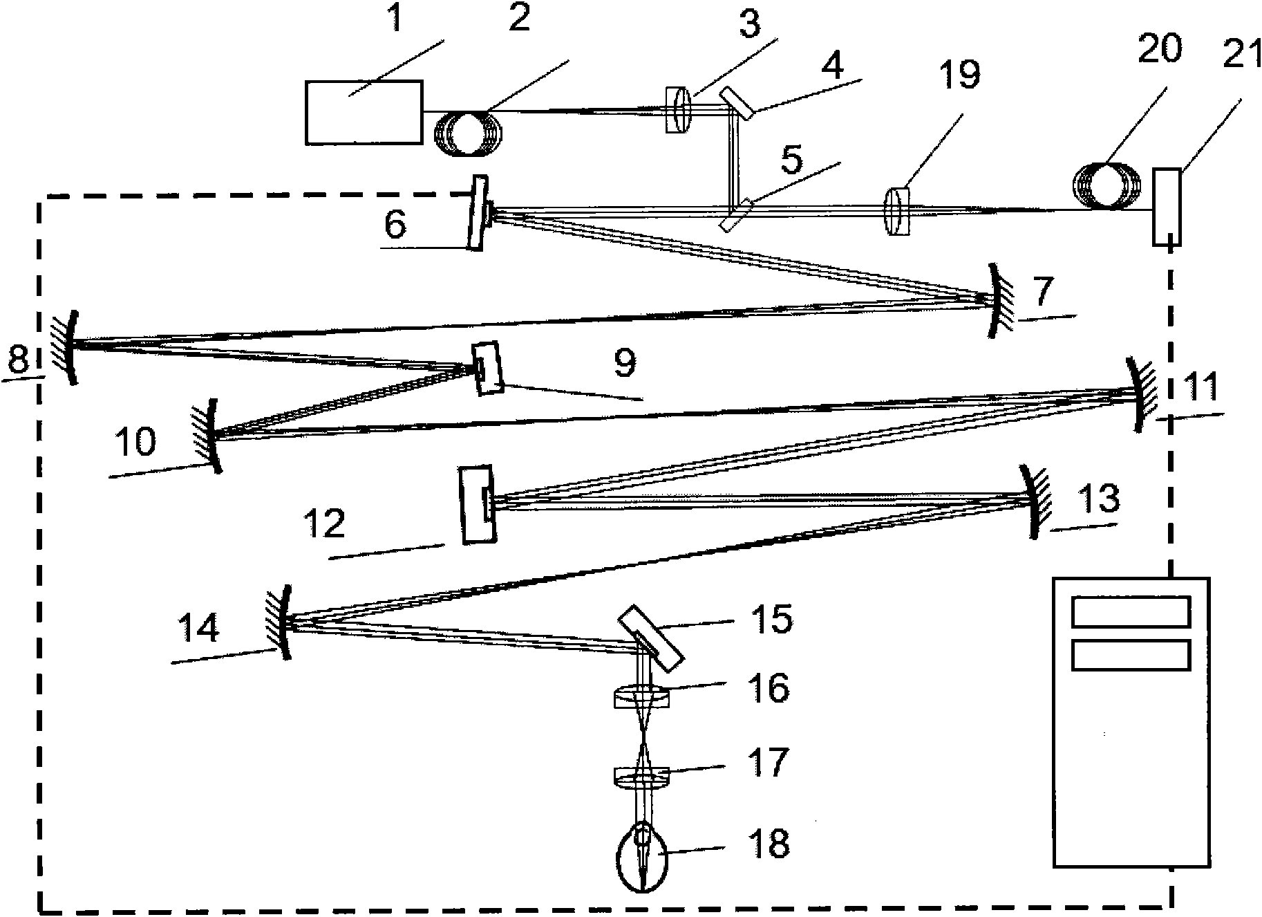
[0033] In the present invention, the two-dimensional imaging scanning module is connected with the wide field of view scanning module through a spherical reflective telescope system (13-14). The optical fiber receiving end module is placed at the terminal of the return optical path of the system, behind the beam splitter (5). The illumination light emitted by the light source module (1-4) enters the human eye after passing through the two-dimensional imaging scanning module (9-12) and the wide-field scanning module (15-17) of the system in sequence, and is diffusely reflected back from the retina of the human eye fundus The signal light returns along the original ...


PUM

PropertyMeasurementUnit
Slopeaaaaaaaaaa

Abstract

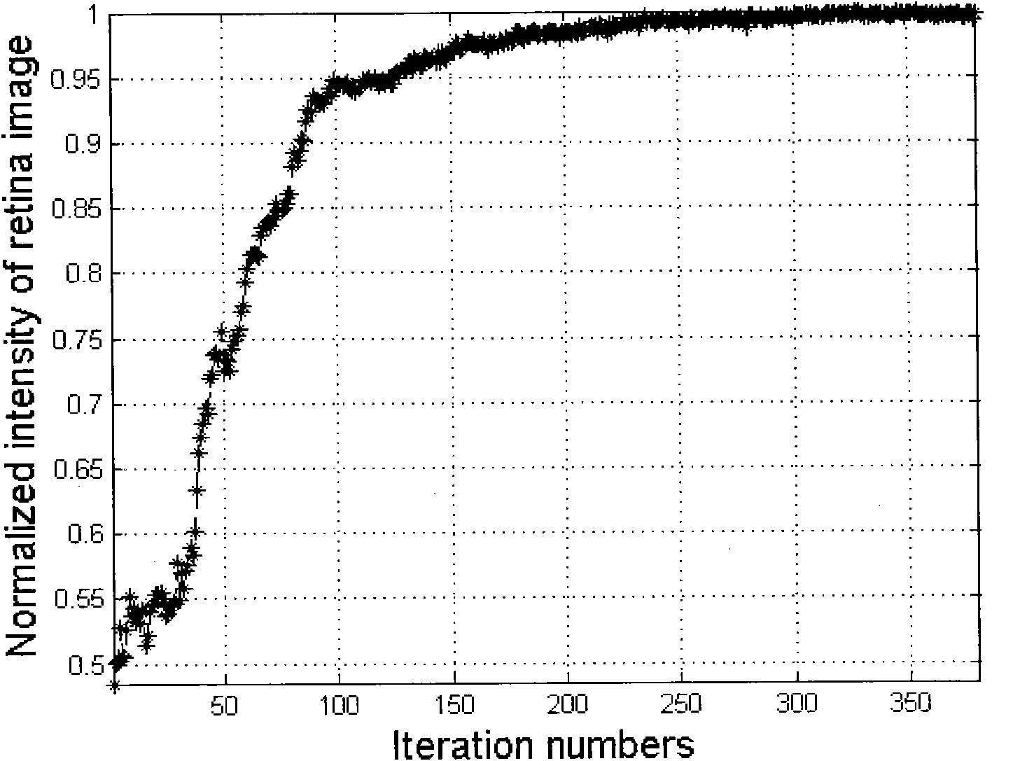
The invention discloses an aberration compensation fundus microscope based on an automatic optimization algorithm. The aberration compensation fundus microscope comprises a light source module, an aberration compensation module, a two-dimensional imaging and scanning module, a wide-field-of-view scanning module and an optical fiber receiving module, wherein, the two-dimensional imaging and scanning module is connected with the wide-field-of-view scanning module through a spherical reflecting telescope system; the optical fiber receiving module is placed at a terminal of a returning optical path of the microscope system and is behind a spectroscope; the illuminating light emitted from the light source module successively passes through the two-dimensional imaging and scanning module and the wide-field-of-view scanning module and then enters eyes; and the diffuse signal light from fundus retina of eyes returns along the original optical path, aberration correction is carried out on the light through an aberration correction module by the automatic optimization algorithm, and then the light enters the optical fiber receiving module through the spectroscope for signal detection. The aberration compensation fundus microscope greatly reduces the cost and the control difficulty of the traditional aberration compensation system, solves the synchronous imaging difficulty in the case of high resolution and wide view field, and greatly improves the imaging view field and the imaging quality of the traditional fundus imaging instrument.

Description

technical field [0001] The present invention relates to a fundus microscope, in particular to an aberration-compensated fundus microscope based on an automatic optimization algorithm. Through the automatic optimization algorithm, the retinal image of the human eye is automatically optimized in real time, and the human eye (or animal eye) retina enables high-resolution video imaging on a cellular scale. Background technique [0002] In the field of retinal microscopic imaging, confocal scanning imaging technology is one of the most important retinal imaging technologies. Confocal scanning technology was first used in biological tissue imaging (Webb RH, Hughes GW.Scanning Laser Ophthalmoscope.Biomedical Engineering, IEEE Transactions on.1981, BME-28(7):488-92.), forming laser confocal in 1987 Scanning imaging equipment (Webb R, Hughes G, Delori F. Confocal scanning laser ophthalmoscope. Applied optics. 1987; 26(8): 1492-9). [0003] The invention patent with the patent numbe...

Claims


Application Information

Patent Timeline
IPC IPC(8): A61B3/13
Inventor 李超宏袁孝周永耀
Owner 苏州六六宏医疗器械有限公司
Learn More