Single-motor-driven all-electric mold closing and moving system and implementation method and application thereof

A single-motor-driven, all-electric technology, applied in the field of electric mold clamping and mold shifting systems, can solve the problems of increasing manufacturing costs, affecting service life, serious heat generation, etc., and achieves the goals of reducing scrap rate, reliable operation and reasonable operation process Effect

Active Publication Date: 2011-04-13
SOUTH CHINA UNIV OF TECH
View PDF5 Cites 8 Cited by
  • Summary
  • Abstract
  • Description
  • Claims
  • Application Information

AI Technical Summary

Problems solved by technology

This kind of electric blow molding machine mainly has the following disadvantages: (1) a separate transmission device is required for mold clamping and mold shifting, which makes the structure huge and complicated, and increases manufacturing costs; (2) the motors are frequently started when the two motors are driven separately Stopping will cause its heat to be serious and affect its service life. The continuous start and stop of the ball screw will make it withstand impact and accelerate wear

Method used


Image

  • Single-motor-driven all-electric mold closing and moving system and implementation method and application thereof
  • Single-motor-driven all-electric mold closing and moving system and implementation method and application thereof
  • Single-motor-driven all-electric mold closing and moving system and implementation method and application thereof

Examples


Embodiment 1

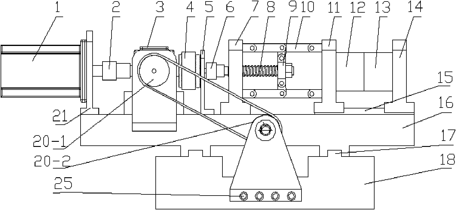
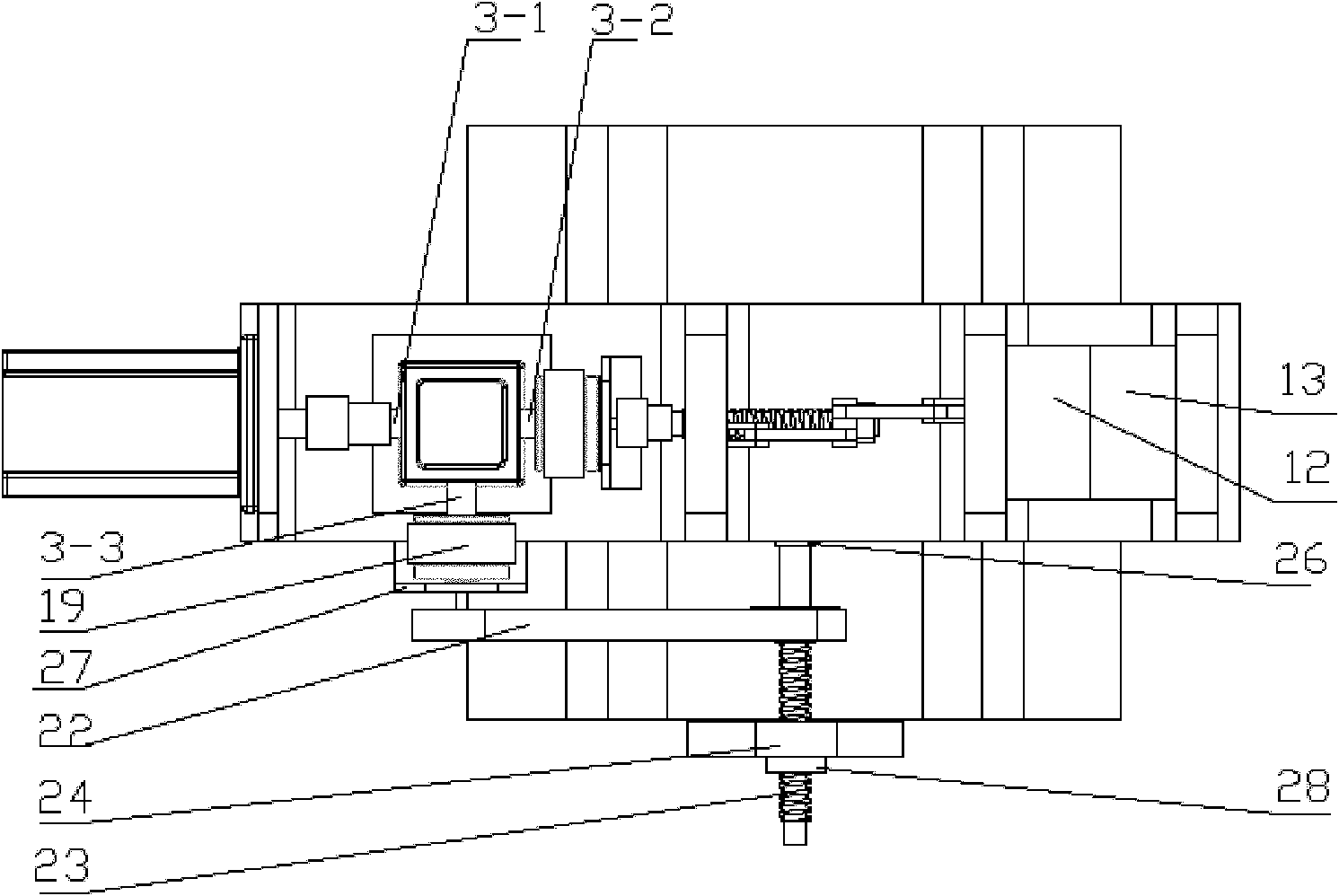
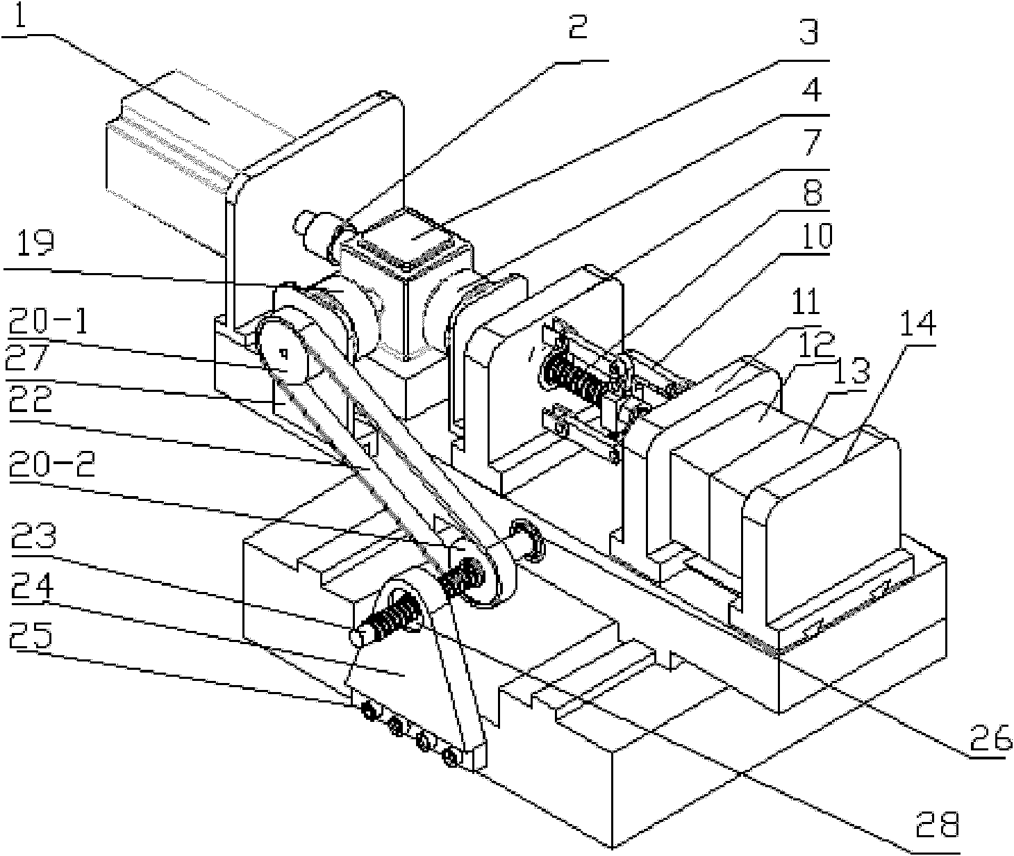
[0030] Figure 1 to Figure 4 The specific structure of the all-electric mold clamping and mold moving system driven by a single motor of the present invention is shown. Depend on figure 1 with figure 2 It can be seen that the all-electric mold clamping and mold moving system driven by a single motor includes a motor 1, a main coupling 2, a steering gear 3, a mold clamping clutch 4, a mold moving clutch 19, a mold clamping coupling 6, a support plate 7, Moving template 11, fixed template 14, clamping ball screw 8, moving mold ball screw 23, timing belt 22, bearing plate 16 and base 18 etc.

[0031] The motor 1 is installed on the plate 21, the output shaft of the motor 1 is connected with the input end 3-1 of the steering gear 3 through the main coupling 2, and the lateral output end 3-2 of the steering gear 3 is connected with the clamping clutch 4, The mold clamping clutch 4 is fixed on the support plate 5, and the output end of the mold clamping clutch 4 is connected wit...

Embodiment 2

[0037] This embodiment is the same as Embodiment 1 except for the following features: the steering gear of this single-motor-driven all-electric mold clamping and mold moving system has three output terminals, and is connected to two sets of mold clamping and mold moving devices at the same time to realize double-station mold clamping .

Embodiment 3

[0039] This embodiment is the same as embodiment 1 except the following features: do not start the mold moving device, only start the mold clamping device, complete the unidirectional mold clamping and locking operation, and can be used for the mold clamping process of the electric injection molding machine (this process does not need mold shifting).


PUM


Abstract

The invention provides a single-motor-driven all-electric mold closing and moving system. The system comprises a motor, a main coupler, a steering device, a mold closing device, a mold moving device, a support plate and a base, wherein the motor is connected with the steering device through the main coupler; the steering device is provided with a plurality of output ends and is respectively connected with the mold closing device and the mold moving device; the motor, the main coupler, the steering device and the mold closing device are connected into a whole and fixed on the support plate; and the support plate and the mold moving device are connected with each other and are arranged on the base. Meanwhile, the invention provides a single-motor-driven all-electric mold closing and moving method realized by the system. The all-electric mold closing and moving system has a compact structure and is easy to popularize and apply, the manufacturing cost and energy consumption can be reduced, materials can be saved, reliability can be improved, and the service life of the motor and a ball screw can be obviously prolonged.

Description

technical field [0001] The present invention relates to an electric mold clamping and mold moving system, in particular to an electric mold clamping and mold moving system for a blow molding machine for polymer materials. Specifically, the same set of motor-steering gear transmission device realizes mold clamping and mold moving functions The all-electric mold clamping and mold moving system driven by a single motor and its realization method and application. Background technique [0002] Polymer material blow molding machinery generally adopts hydraulic technology, that is, hydraulic transmission is used for mold clamping and mold removal. In recent years, electric blow molding machinery has been gradually developed and applied. Compared with hydraulic blow molding machinery, electric blow molding machinery has the advantages of higher control precision for clamping speed and stroke, faster response, lower energy consumption and noise. But the structure of existing electr...

Claims


Application Information

Patent Timeline
Patent Type & Authority Applications(China)
IPC IPC(8): B29C49/42B29C49/56B29C45/64
Inventor 黄汉雄李为平
Owner SOUTH CHINA UNIV OF TECH
Why Eureka
Try Eureka