Fluid resistance reduction composition

A composition and fluid technology, applied in the direction of fluid flow, mechanical equipment, etc., can solve the problems of low drag reduction efficiency, high price, high shear stress resistance, etc. less harmful effects

Inactive Publication Date: 2011-04-13
陈光洋
View PDF3 Cites 3 Cited by
  • Summary
  • Abstract
  • Description
  • Claims
  • Application Information

AI Technical Summary

Problems solved by technology

However, the disadvantages of using polymers as drag reducers are that they are more expensive, not resistant to high shear stress, easy to degrade, and the drag reduction efficiency will decrease when they are used repeatedly or transported over long distances

Method used


Image

  • Fluid resistance reduction composition
  • Fluid resistance reduction composition
  • Fluid resistance reduction composition

Examples


Embodiment

[0042] Embodiment: drag reducing agent drag reduction experiment

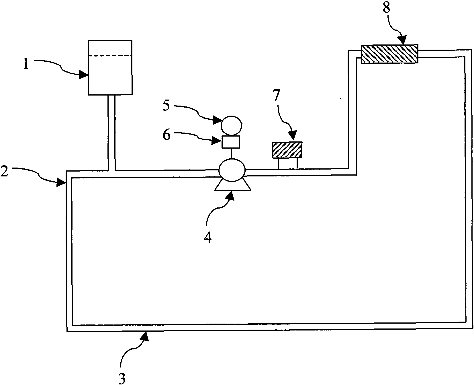
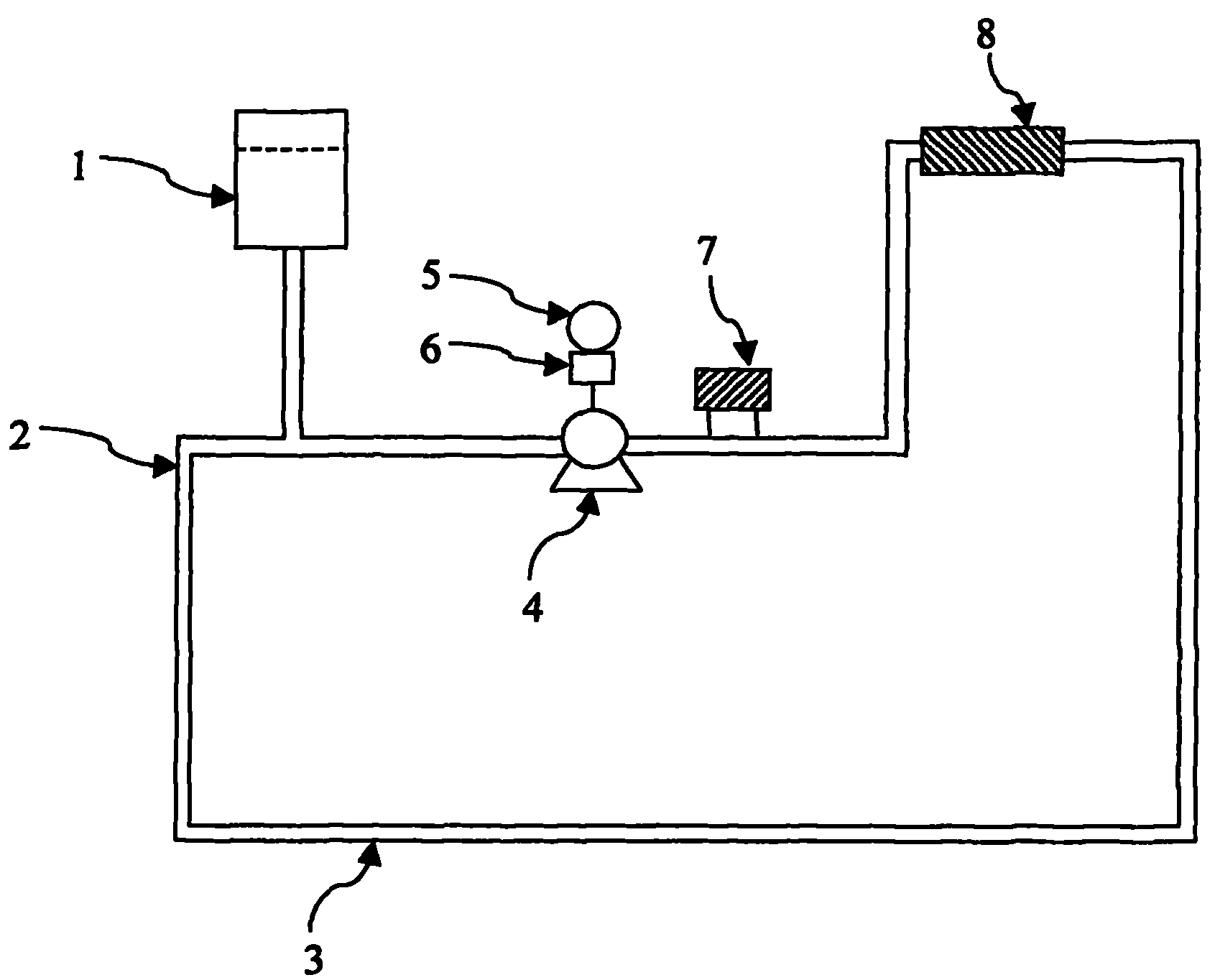
[0043] The present invention utilizes a self-made fluid flow circuit system as an evaluation of the fluid drag reducing composition of the present invention for reducing fluid resistance and reducing pump power consumption. For a diagrammatic description of the system, please refer to figure 1 .

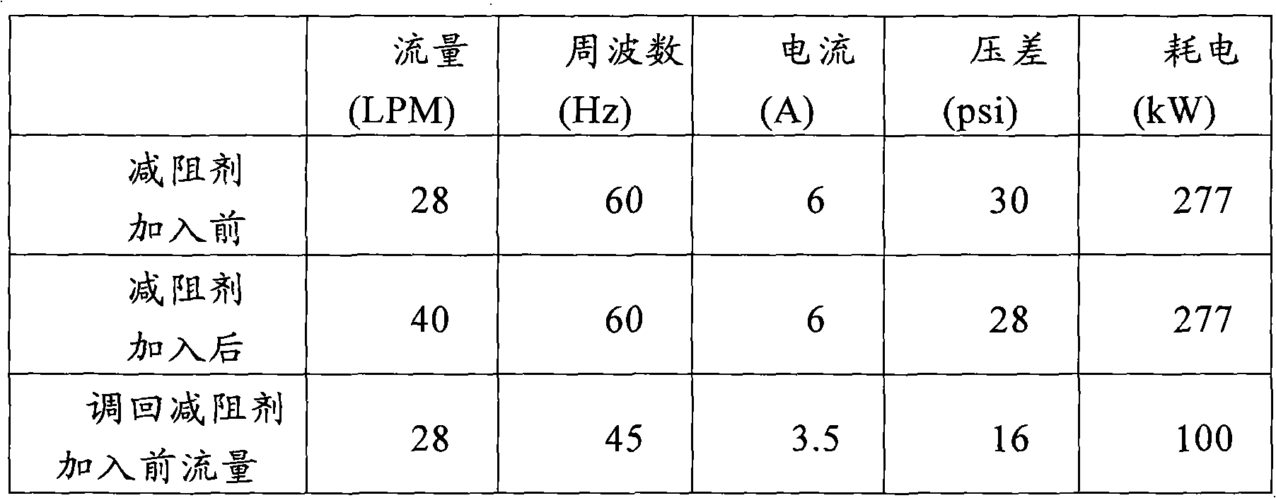
[0044] The composition weight percent of the drag reducing agent that embodiment uses is: water 41.5%, 2-hydroxybenzoic acid sodium 24%, sodium benzoate 6%, sodium nitrite 14%, cetyl trimethyl ammonium chloride 10%, oil 2% Trimethylamide, 2% Octadecyltrimethylammonium Chloride and 0.5% Sodium Hydroxide. The drag reducer is added to the water-containing expansion tank 1 in an amount of 0.1% to 0.5% relative to the water, and the added amount can be adjusted according to parameters such as water quality, water temperature, pipe diameter, pipe length, and lift. The system includes a 6.5m 3 / 4 hour hard pipe 2 and a 20m ...


PUM


Abstract

Provided is a fluid resistance reduction composition comprising: a nitrite, an interfacial agent, a corresponding ionic compound, an electrolyte and an aqueous phase medium. Therefore, the fluid resistance reduction composition provided in the present invention is capable of effectively reducing fluid resistance and lowering energy consumption, thereby indirectly reducing carbon emission.

Description

technical field [0001] The invention relates to a fluid drag reducing composition, in particular to a drag reducing agent used in the field of fluid delivery. Background technique [0002] Energy saving and carbon reduction are slogans put forward by various countries in response to the depletion of energy sources. Various researches are underway in order to achieve the goal of saving energy consumption and reducing carbon emissions; while in air conditioning equipment, heating pipelines, petroleum pipelines, chemical equipment, In industrial processes such as power systems and mortar transportation, pump power consumption accounts for a major part of the energy consumption of the entire system. Therefore, how to minimize pump power loss is the main means for these systems to reduce energy consumption and increase delivery capacity, and it is also an important issue that plagues enterprises. [0003] The frictional drag of the fluid restricts the flow of the fluid in the pi...

Claims


Application Information

Patent Timeline
Patent Type & Authority Applications(China)
IPC IPC(8): F15D1/06
Inventor 陈光洋
Owner 陈光洋
Why Eureka
Try Eureka