System and method for temperature reduction and pressure stabilization of liquefied natural gas storage tank

A liquefied natural gas and liquid nitrogen storage tank technology, which is applied in the field of liquefied natural gas storage, can solve the problems of unsuitable liquefied natural gas storage tanks, not widely used, contrary to liquefied natural gas, etc., and achieves a simple structure, easy-to-understand structure and low cost. Effect

Inactive Publication Date: 2011-04-13
SOUTH CHINA UNIV OF TECH
View PDF5 Cites 18 Cited by
  • Summary
  • Abstract
  • Description
  • Claims
  • Application Information

AI Technical Summary

Problems solved by technology

Although these two technologies can initially solve the problem of potential safety hazards, there are defects in these two technologies: direct combustion of BOG gas violates the purpose of storing liquefied natural gas itself, and is not suitable for long-term storage of liquefied natural gas storage tanks
However, the process of changing the structure of the storage tank with this technology is more complicated, and the manufacturing of this storage tank requires more costs, and it is not widely used
In addition, this technology does not completely avoid the generation of BOG gas, so it is not suitable for LNG storage tanks that require long-term storage, and is only suitable for LNG carriers

Method used


Image

  • System and method for temperature reduction and pressure stabilization of liquefied natural gas storage tank
  • System and method for temperature reduction and pressure stabilization of liquefied natural gas storage tank
  • System and method for temperature reduction and pressure stabilization of liquefied natural gas storage tank

Examples


Embodiment 1

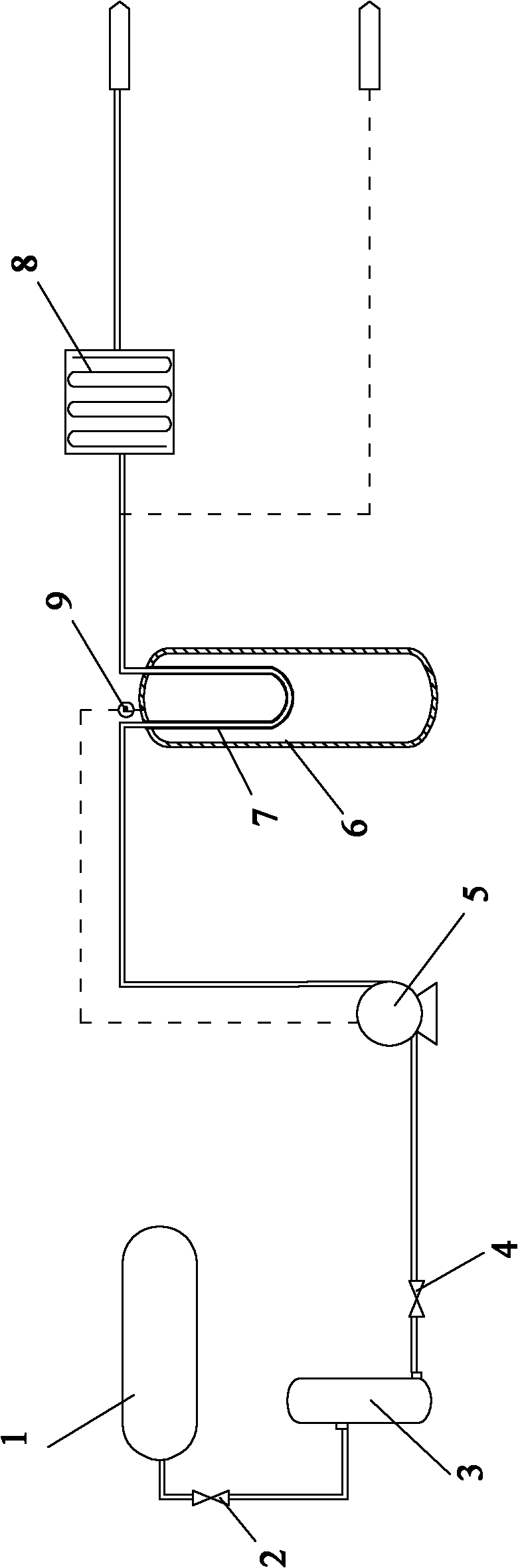
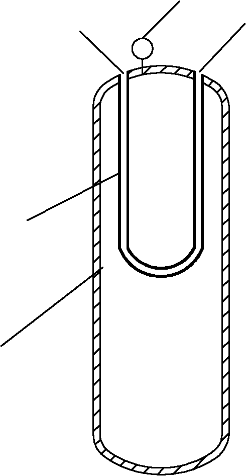
[0034] Such as figure 1 As shown, the cooling and stabilizing system for the LNG storage tank includes a liquid nitrogen delivery device, an LNG storage tank 6 and an exhaust pipe, such as figure 2 As shown, the liquefied natural gas storage tank 6 is provided with a heat exchange tube 7, the inlet 10 of the heat exchange tube 7 is connected to the liquid nitrogen delivery device through a pipeline, and the outlet 11 is connected to an exhaust pipeline through a pipeline; The tank 6 is provided with a pressure sensor 9 connected to a liquid nitrogen conveying device, and the exhaust pipe is provided with a vaporizer; the liquid nitrogen conveying device is externally connected to a liquid nitrogen source 1.

[0035] The vaporizer is an air temperature vaporizer 8.

[0036] The liquid nitrogen delivery device includes a liquid nitrogen storage tank 3 and a pump 5. The liquid nitrogen storage tank 3 is externally connected to a liquid nitrogen source 1. One end of the pump 5 is conne...

Embodiment 2

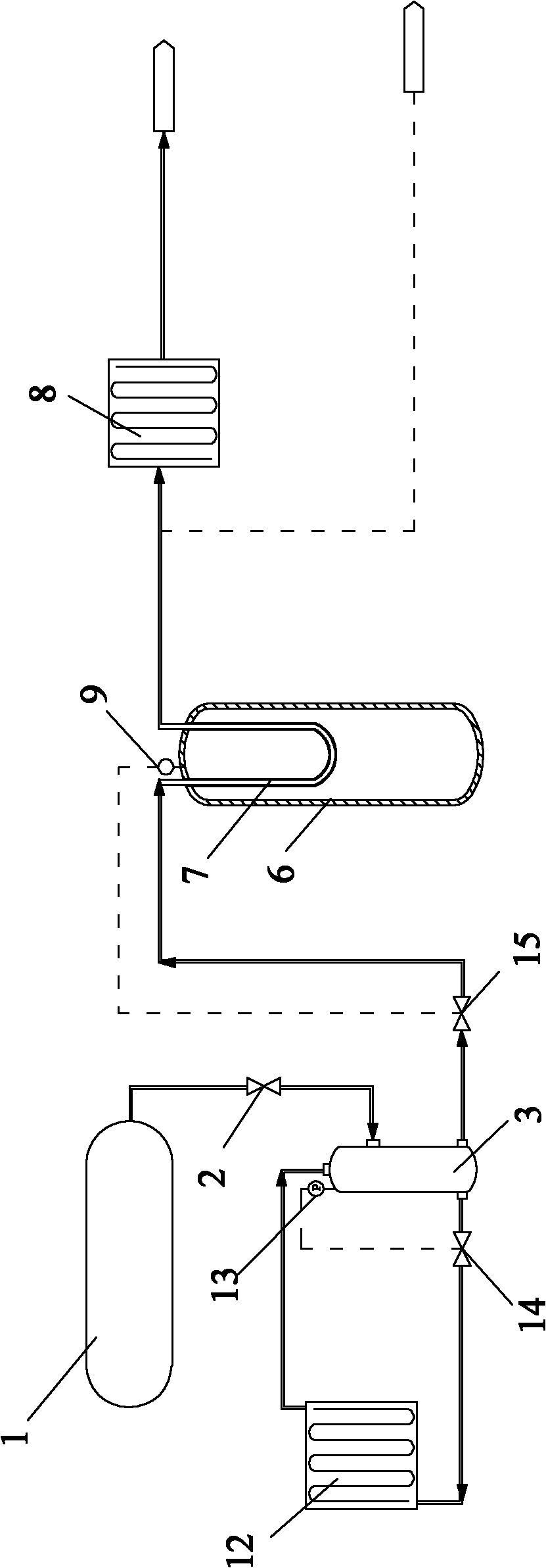
[0046] The other features of this embodiment are the same as those of the first embodiment except for the following features: image 3 As shown, the liquid nitrogen delivery device includes a liquid nitrogen storage tank 3 and a self-pressurizing vaporizer 12. The liquid nitrogen storage tank 3 is respectively connected to the liquid nitrogen source 1 and the inlet of the heat exchange tube 7 through pipelines, and The nitrogen storage tank 3 is provided with a vaporization inlet and a vaporization outlet. The self-pressurized vaporizer 12 is connected to the vaporization inlet and the vaporization outlet of the liquid nitrogen storage tank 3 through pipes; on the pipe connecting the self-pressurized vaporizer 12 and the vaporization inlet A vaporization valve 14 is provided, a pressure sensor 13 is provided on the liquid nitrogen storage tank 3, and the vaporization valve 14 is connected to the pressure sensor 13;

[0047] The pipeline connecting the liquid nitrogen source 1 and...

Embodiment 3

[0053] The other features of this embodiment are the same as those of the first embodiment except for the following features: the length of the heat exchange tube in the height direction of the LNG storage tank is 5m. The heat exchange tube is a serpentine coil.


PUM


Abstract

The invention provides a system for temperature reduction and pressure stabilization of a liquefied natural gas storage tank, comprising a liquid nitrogen delivery device, a liquefied natural gas storage tank and a discharge duct, wherein the liquefied natural gas storage tank is internally provided with a heat exchange tube; the inlet of the heat exchange tube is connected with the liquid nitrogen delivery device through a pipeline, and the outlet of the heat exchange tube is connected with the discharge duct through a pipeline; the liquefied natural gas storage tank is provided with a pressure sensor connected with the liquid nitrogen delivery device; the discharge duct is internally provided with a vaporizer; and the liquid nitrogen delivery device is externally connected with a liquid nitrogen source. The invention also provides a method for temperature reduction and pressure stabilization of the liquefied natural gas storage tank, which is realized by the system. In the system provided by the invention, the temperature and pressure conservation functions of the liquefied natural gas storage tank can be realized through the arrangement of the heat exchange tube in the liquefied natural gas storage tank, thus the structure is simple and easy to understand, and the system is suitable for various liquefied natural gas storage tanks and has low design cost and the like.

Description

Technical field [0001] The invention relates to liquefied natural gas storage technology, in particular to a temperature-reducing and stabilizing system and method for liquefied natural gas storage tanks. Background technique [0002] When LNG is in use, it is generally stored in LNG storage tanks (ie, LNG storage tanks); while in the use of LNG storage tanks, as the LNG storage tanks are used for longer, they will absorb heat from the atmosphere , So that the liquefied natural gas is vaporized into BOG gas (ie boil-off gas or gaseous natural gas), which leads to an increase in the pressure in the liquefied natural gas storage tank, resulting in potential safety hazards. [0003] In view of the above problems, the current solutions mainly include the following four: (1) Directly discharge BOG gas and burn it on site to reduce the pressure in the LNG storage tank; (2) Directly incorporate BOG gas into the pipeline network for use; 3) After the BOG gas is exported to pressurized liq...

Claims


Application Information

Patent Timeline
Patent Type & Authority Applications(China)
IPC IPC(8): F17D5/00F17D3/01F17C1/00
Inventor 何奕霏解东来
Owner SOUTH CHINA UNIV OF TECH
Why Eureka
Try Eureka