Radiating structure and manufacturing method thereof as well as electronic device with radiating structure

A technology of heat dissipation structure and heat sink, which is used in printed circuit components, cooling/ventilation/heating transformation, and assembling printed circuits with electrical components. The problem of high threshold, to achieve the effect of low curing process difficulty, good heat dissipation effect and low process cost

Inactive Publication Date: 2012-08-22
MOBILE ANTENNA TECH SHENZHEN
View PDF3 Cites 0 Cited by
  • Summary
  • Abstract
  • Description
  • Claims
  • Application Information

AI Technical Summary

Problems solved by technology

The heat dissipation effect is good, but it requires large-area copper-based 400 and circuit board welding. The welding process is difficult, and it is easy to have air hollows that make it impossible to adhere tightly; the amount of tin is not easy to control, and the via holes are easy to leak tin to the front, which will affect the circuit board components. Welding and Appearance
This method is costly, and the threshold of process technology is high. Only a few manufacturers have the ability to implement this process, and it affects the yield rate in mass production.
[0006] In summary, the existing heat dissipation structure obviously has inconvenience and defects in actual use, so it is necessary to improve it

Method used


Image

  • Radiating structure and manufacturing method thereof as well as electronic device with radiating structure
  • Radiating structure and manufacturing method thereof as well as electronic device with radiating structure
  • Radiating structure and manufacturing method thereof as well as electronic device with radiating structure

Examples


Embodiment Construction

[0036] In order to make the object, technical solution and advantages of the present invention clearer, the present invention will be further described in detail below in conjunction with the accompanying drawings and embodiments. It should be understood that the specific embodiments described here are only used to explain the present invention, not to limit the present invention.

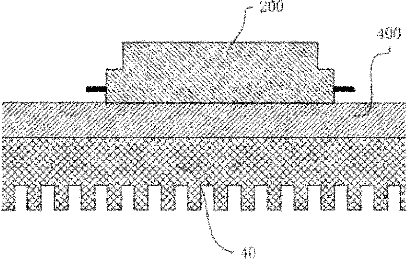
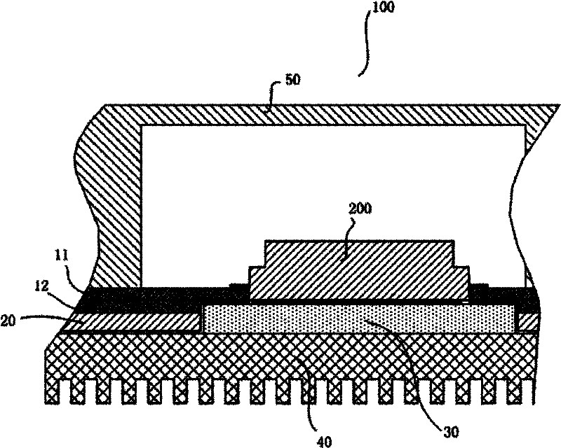
[0037] Such as figure 2 As shown, a heat dissipation structure 100 of the present invention is used for heat dissipation of a power amplifier 200 . Obviously, the heat dissipation structure 100 can not only be used for heat dissipation of the power amplifier 200, but also can be used for heat dissipation of other electronic components.

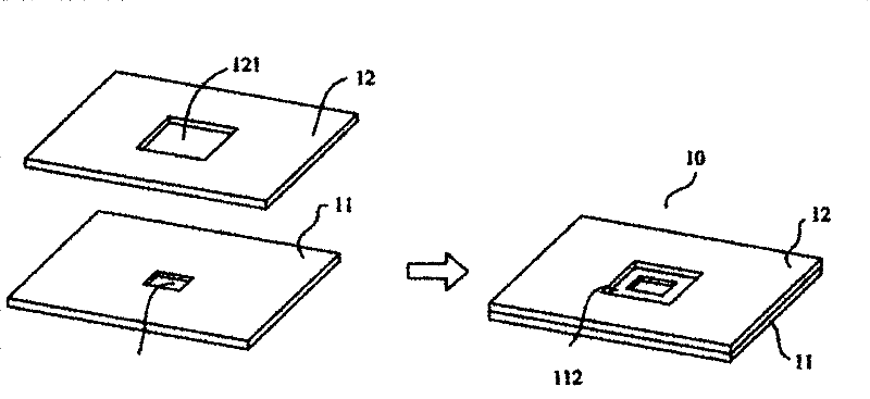
[0038] The double-layer circuit board 10 includes a first circuit board 11 and a second circuit board 12 bonded to each other. Such as image 3 As shown, the first circuit board 11 is provided with a first opening 111, and the second circuit board 12 is corresp...


PUM


Abstract

The invention discloses a radiating structure, which comprises a double-layer circuit board, a bottom shell and a radiating fin, wherein the double-layer circuit board comprises a first circuit board and a second circuit board which are mutually fit; the first circuit board is provided with a first opening; the second circuit board is correspondingly provided with a second opening bigger than thefirst opening; a fixed connection zone is formed between the first opening and the second opening by the first circuit board; the bottom shell is fit below the second circuit board and is correspondingly provided with a third opening with the size equal to that of the second opening; the radiating fin is fixedly arranged below the bottom shell; a metal substrate with an adaptive shape is embeddedin the space formed by the second opening and the third opening; the upper surface of the metal substrate is fixedly connected with the fixed connection zone and the lower surface thereof is contacted with the radiating fin; and an electronic component is embedded in the first opening and the radiating part of the electronic component is fixedly connected with the upper surface of the metal substrate. The invention correspondingly provides an electronic device with the radiating structure and a manufacturing method of the radiating structure. The invention has better radiating effect, lower cost and higher product reliability.

Description

technical field [0001] The invention relates to the technical field of wireless communication, in particular to a heat dissipation structure, a manufacturing method thereof, and an electronic device with a heat dissipation structure. Background technique [0002] The radio frequency power amplifier is a key component in the wireless communication system. In order to ensure the coverage distance and communication quality of the wireless communication, the transmitter needs to output a large enough radio frequency power, and the main function of the radio frequency power amplifier is to transfer the Linear power amplification for small radio frequency signals. When the RF power amplifier is working, it has a certain power dissipation and will generate a certain amount of heat, which will affect the working status and reliability of the power amplifier. Therefore, the heat dissipation design of the RF power amplifier is quite critical, and it is an important link in the reliab...

Claims


Application Information

Patent Timeline
Patent Type & Authority Patents(China)
IPC IPC(8): H05K7/20H05K1/02H05K3/30
Inventor 雷小勇闫亚琴林伟新
Owner MOBILE ANTENNA TECH SHENZHEN
Why Eureka
Try Eureka