
Magnet unit, and magnetron sputtering device

一种磁控溅射装置、磁铁单元的技术,应用在溅射镀覆、电气元件、离子注入镀覆等方向,能够解决限制、不能调整磁轨长度等问题,达到膜厚分布均匀的效果

Active Publication Date: 2011-04-27
CANON ANELVA CORP
View PDF1 Cites 9 Cited by
  • Summary
  • Abstract
  • Description
  • Claims
  • Application Information

AI Technical Summary

Problems solved by technology

Therefore, the length of the magnetic track cannot be adjusted only by forming T-shaped parts at both ends of the center magnet.
In order to increase the length of the magnetic track at both ends of the target, such as Figure 16 As shown, the length A in the width direction of the T-shaped part must be increased, but this length A is limited by the width B of the magnet

Method used


Image

  • Magnet unit, and magnetron sputtering device
  • Magnet unit, and magnetron sputtering device
  • Magnet unit, and magnetron sputtering device

Examples


no. 1 Embodiment approach

[0044] Next, refer to Figure 4 The magnet unit 10 of the first embodiment mounted in the sputtering apparatus 1 described above will be described. Figure 4 It is a top view showing the structure of the magnet unit of 1st Embodiment.

[0045] Such as Figure 4 As shown, the magnet unit 10 of the present embodiment has a yoke 20 having the same shape (rectangular shape) as the target 6 and made of a ferromagnetic plate material on the back side of the cathode electrode. The yoke is provided with an annular outer magnet 30 arranged along the outline of the target 6 , and an inner magnet 40 arranged in the outer magnet and having a polarity different from that of the outer magnet 30 .

[0046] As described above, the main body (first magnetic pole) 31 of the outer peripheral magnet 30 is formed in a ring shape (rectangular frame shape) along the outline of the target 6 .

[0047] The inner magnet 40 arranged in the main body (first magnetic pole) 31 of the outer peripheral ma...

no. 2 Embodiment approach

[0059] Next, refer to Figure 7 The magnet unit 50 of the second embodiment mounted in the sputtering apparatus 1 described above will be described. Figure 7 It is a plan view which shows the structure of the magnet unit of 2nd Embodiment. In addition, the same code|symbol is attached|subjected and demonstrated about the same component as 1st Embodiment.

[0060] Such as Figure 7 As shown, in the magnet unit 50 of the second embodiment, the structures of the yoke 20 and the outer peripheral magnet 30 are the same as those of the first embodiment. That is, a yoke 20 having the same rectangular shape as the target 6 and made of a ferromagnetic plate is provided on the back side of the cathode electrode. In addition, the main body (first magnetic pole) 31 of the outer peripheral magnet 30 is formed in a rectangular frame shape along the outline of the target 6 . In addition, n−1 protruding magnetic pole portions (second magnetic poles) 32 are protruded from both ends of the...

Embodiment 1

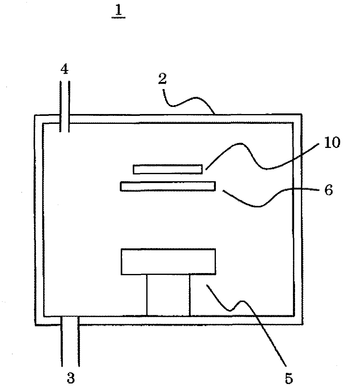
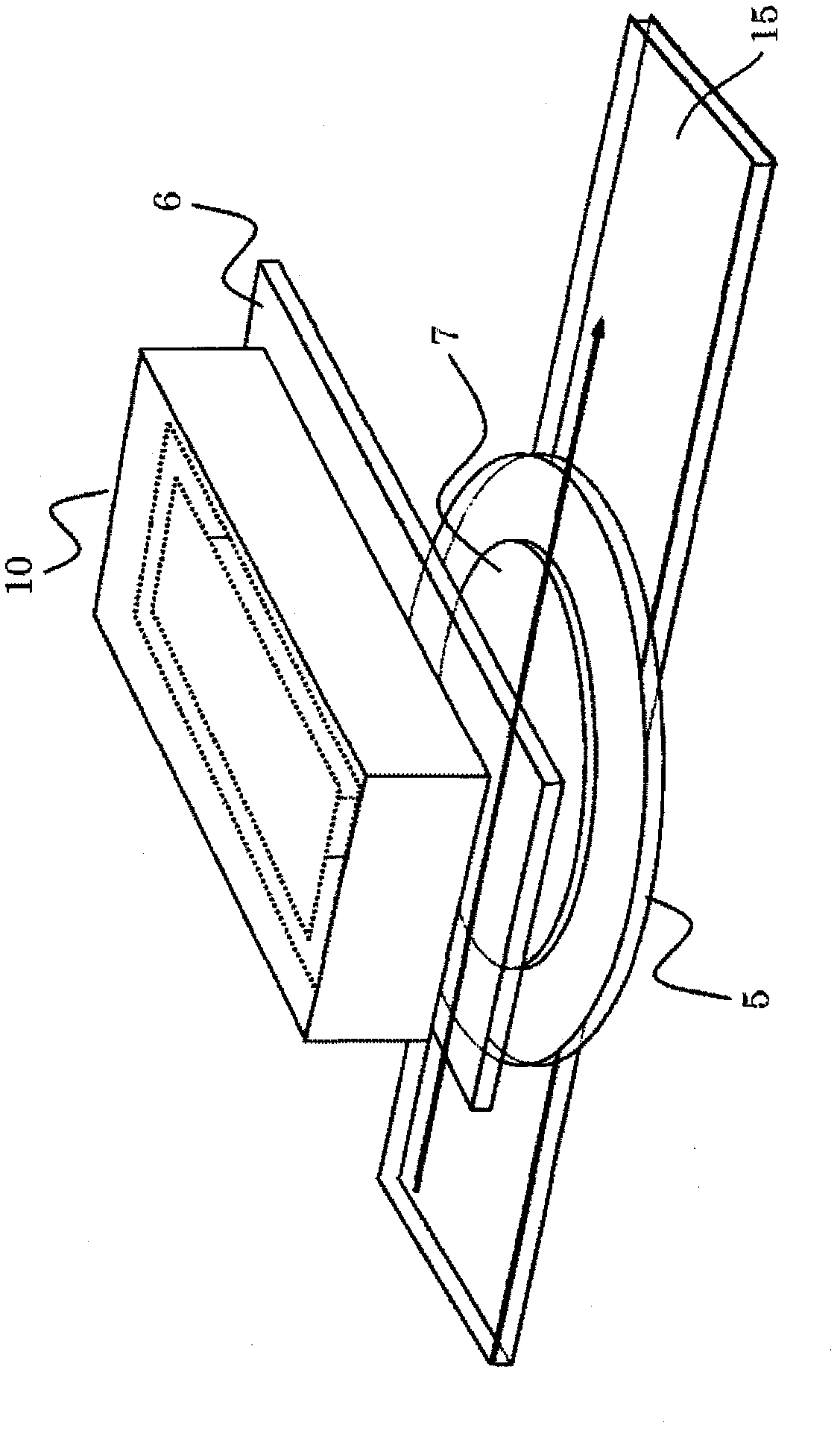
[0074] In Example 1, using figure 1 The sputtering device 1 and figure 2 The transport mechanism (guide rail) 15 supports a plurality of silicon substrates on the guide rail, moves the guide rail in a direction perpendicular to the longitudinal direction of the target, and forms a titanium nitride film on each substrate.

[0075] Using titanium (Ti) as the target 6 supported on the cathode electrode, Ar, N 2 The mixed gas is introduced into the vacuum container 2 as a process gas.

[0076] Figure 10 It is an explanatory diagram showing the state of film formation in Example 1 in relation to the prior art. Such as Figure 10 As shown in (A) and (C), when a conventional magnet unit is mounted in the sputtering apparatus 1, the film thickness changes in the outer peripheral portions of the substrate corresponding to both ends in the longitudinal direction of the target 6 are observed. Thin.

[0077] In contrast to this, as Figure 10 As shown in (B) and (D), when the ab...


PUM


Abstract

The invention provides a magnet unit and a magnetron sputtering device. Disclosed is a magnet unit which can homogenize the thickness distribution of a thin film to be formed on a substrate, without increasing the length and width of a target. The magnet unit (10) comprises an annular outer magnet (30) arranged over a yoke (20) on the back side of a cathode electrode and along the contour of a target (6), and an inner magnet (40) arranged in the annular outer magnet and made different in polarity from the outer magnet, whereby the tangents of magnetic lines of force (M) generated over the target form the magnetic tracks (MT) of a set of areas parallel to the target face. The magnet unit (10) also comprises extending magnetic poles (41) of an n-number (n indicates a positive integer of 2 or more) extending from the central portion of the inner magnet and approaching the two longitudinal ends of the outer magnet, and protruding magnetic poles (32) of a (n-1)-number protruding longitudinally inward from the inner sides of the two ends of the outer magnet and positioned between the extending magnetic poles of the n-number. The extending magnetic poles of the n-number and the protruding magnetic poles of the (n-1)-number form folded-back sections (U) of a (2n-1)-number at the two longitudinal ends of the magnetic track.

Description

technical field [0001] The present invention relates to an improvement in the structure of a magnet unit disposed on the back side of a cathode electrode for supporting a target on the front side during sputtering, and a magnetron sputtering (magnetron sputtering) system having the magnet unit. sputtering) device. Background technique [0002] In the magnetron sputtering apparatus, a magnetron is generated on a discharge surface of a target by a magnet unit disposed on the back side of a cathode electrode for supporting a target, and then plasma is enclosed to make the plasma have a high density. Then, by causing ions of the plasma generated by this device to collide with the target, the substances on the target are bounced off and attached to the substrate to form a thin film. [0003] Therefore, the film formation rate strongly depends on the intensity of the leakage magnetic field and the intensity of the electric field applied to the target. In particular, the magnetro...

Claims


Application Information

Patent Timeline
Patent Type & Authority Applications(China)
IPC IPC(8): C23C14/35
CPCH01J37/3452H01J37/3405C23C14/35
Inventor 远藤彻哉爱因斯坦·诺埃尔·阿巴拉
Owner CANON ANELVA CORP
Learn More