Liquid crystal display (LCD)

A liquid crystal display and liquid crystal panel technology, applied in the direction of instruments, nonlinear optics, optics, etc., can solve problems such as difficulty in ensuring flatness, affecting optical effects, and insufficient strength, so as to overcome difficulties in ensuring flatness, realize integration, and overall The effect of increasing strength

Active Publication Date: 2011-05-04
BOE TECH GRP CO LTD
View PDF0 Cites 33 Cited by
  • Summary
  • Abstract
  • Description
  • Claims
  • Application Information

AI Technical Summary

Problems solved by technology

[0004] However, in the process of realizing the present invention, the inventors have found that there are at least the following problems in the prior art: for large-scale liquid crystal displays, the thickness of the light guide plate often determines the thickness of the entire device. When installing and fixing the light guide plate, in order to ensure its Flatness. At present, the thickness of large-sized light guide plates is generally between 4mm and 8mm. For light guide plates with a thickness below 4mm, although the thickness can meet the requirements of thinning, it is not easy to ensure flatness due to insufficient strength, which affects the optical effect. , and it is difficult to install and fix

Method used


Image

  • Liquid crystal display (LCD)
  • Liquid crystal display (LCD)
  • Liquid crystal display (LCD)

Examples


Embodiment 1

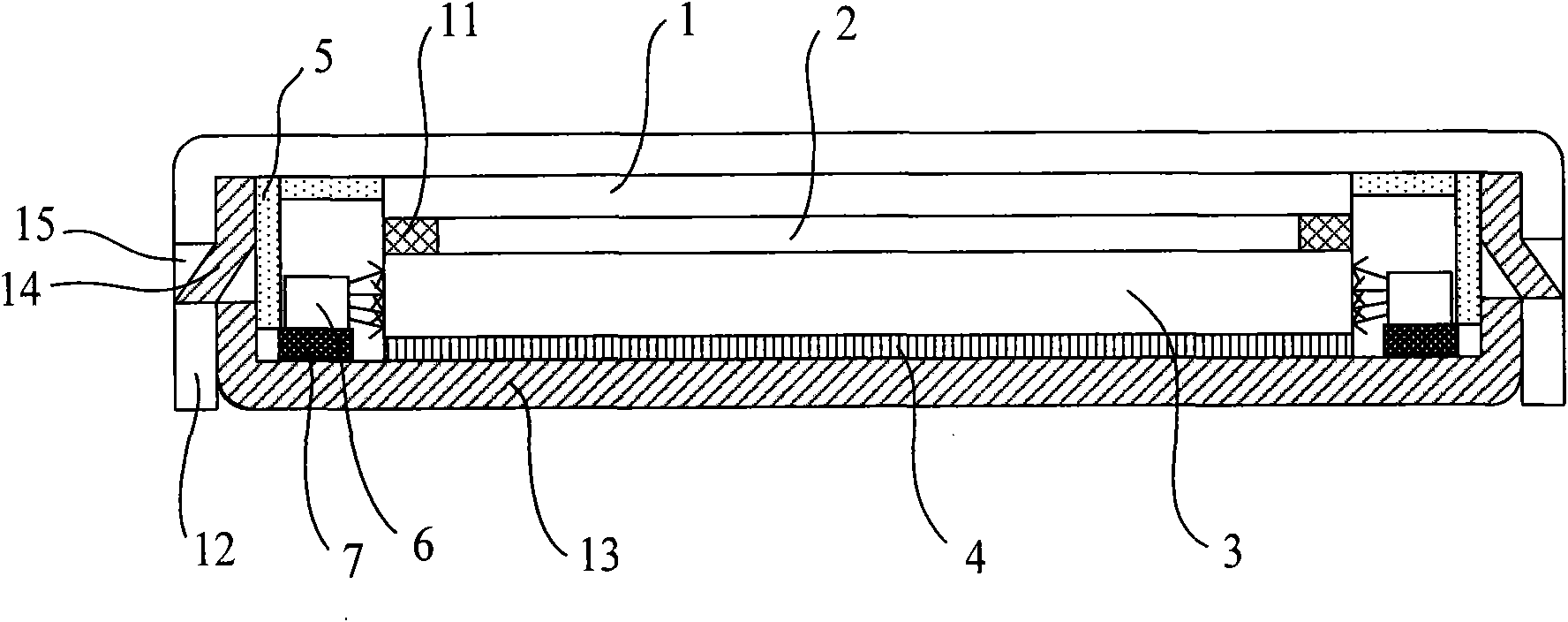
[0040] figure 1 Embodiment 1 of the present invention provides a schematic diagram of a side-view structure of a liquid crystal display when the light source adopts a side-emitting type. The liquid crystal display of this embodiment includes: a liquid crystal panel 1 , an optical film layer 2 , a backlight module, a bottom backplane 13 and an upper cover 12 . Among them, the backlight module at least includes a light guide plate 3, a first reflection sheet 4, a light source 6 and a light source circuit board 7; the optical film layer 2 can be a composite film with a diffusion effect and a light enhancement effect, or at least include a prism sheet and a Diffusion sheets and other membranes on the lower side; the first reflection sheet 4 is located on the upper surface of the bottom back plate 13, the light guide plate 3 is located on the upper surface of the first reflection sheet 4, the optical film layer 2 is located on the upper surface of the light guide plate 3, and the l...

Embodiment 2

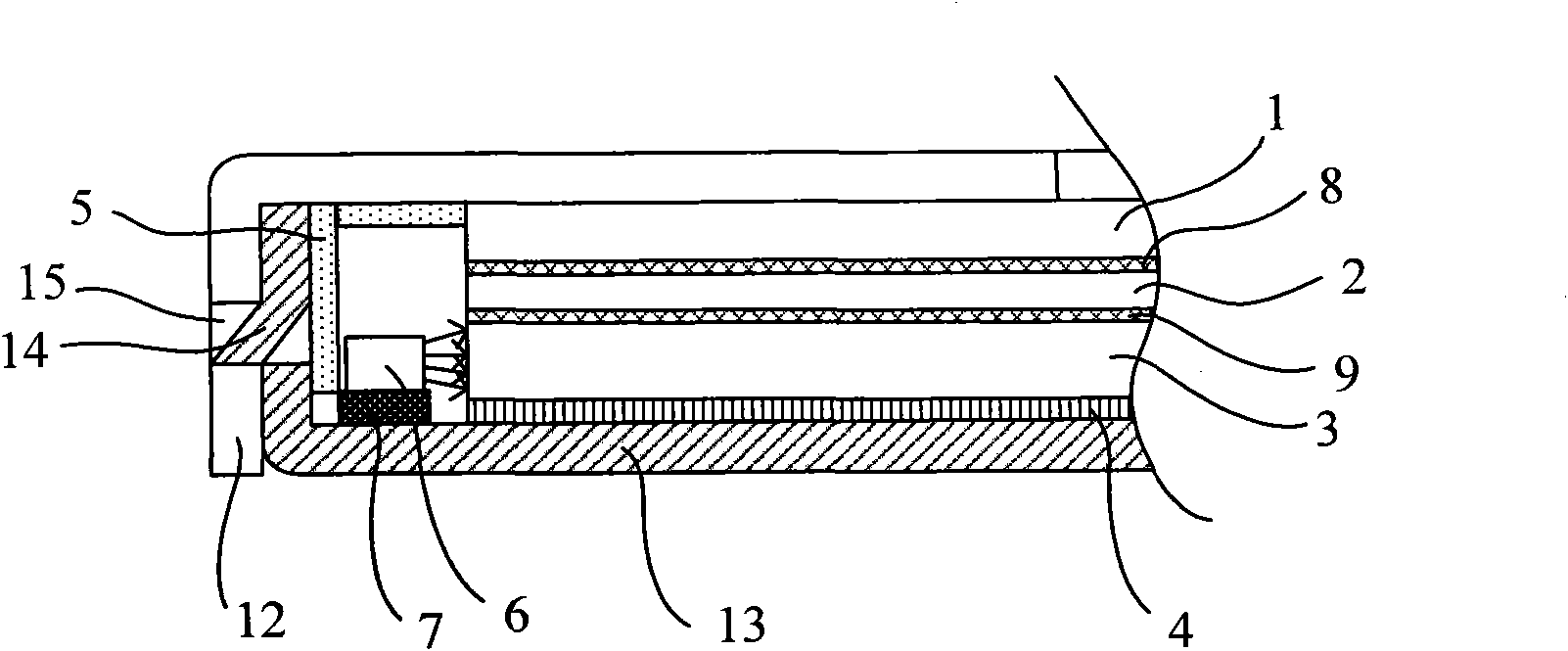
[0046] figure 2 A schematic diagram of a side-view structure of a liquid crystal display when the light source provided by Embodiment 2 of the present invention adopts a side-emitting type. The difference between this embodiment and Embodiment 1 is that: the optical film layer 2 is a layer of composite film; the light guide plate 3 and the composite film are bonded together by the second adhesive layer 9; the composite film and the liquid crystal panel 1, bonded together by the third adhesive layer 8.

[0047] There can be multiple specific bonding methods for the above-mentioned adhesive layer. For example, from the perspective of the coating position of the adhesive layer, it is preferred to:

[0048] The second adhesive layer 9 is evenly coated on the entire contact surface between the light guide plate 3 and the composite film; the third adhesive layer 8 is evenly coated on the entire contact surface between the composite film and the liquid crystal panel 1 superior. T...

Embodiment 3

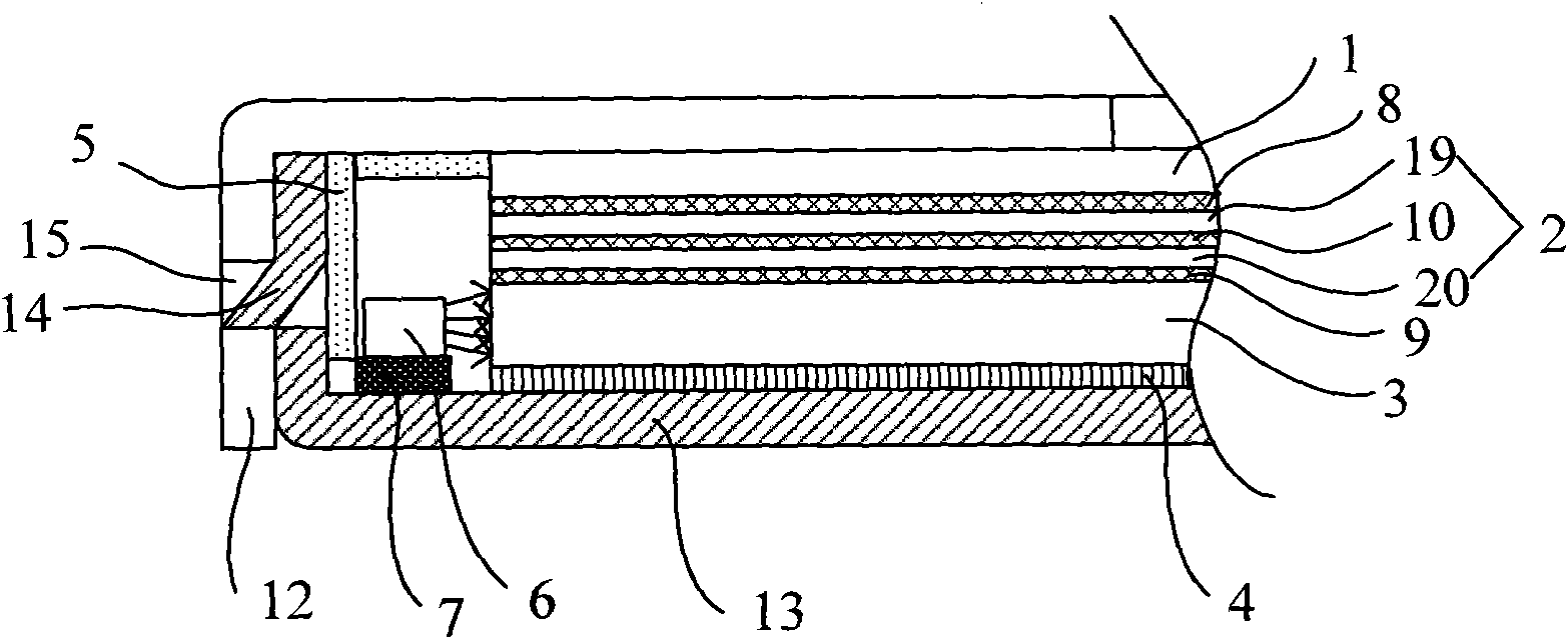
[0052] image 3 A schematic diagram of a side-view structure of a liquid crystal display when the light source provided by Embodiment 3 of the present invention adopts a side-emitting type. The difference between this embodiment and Embodiment 2 is that: the light guide plate 3 and the optical film layer 2 are bonded together through the second adhesive layer 9; the optical film layer 2 and the liquid crystal panel 1 are bonded together through the third adhesive layer 9. The layers 8 are bonded together; the films in the optical film layer 2 are bonded together through the fourth adhesive layer 10 .

[0053] The films of the above-mentioned optical film layer can have various combinations, for example, a combination of a diffusion film, a prism film and a polarizer from the side of the light guide plate to the side of the liquid crystal panel.

[0054] In this embodiment, the optical film layer 2 includes a diffusion sheet 20 located on the upper surface of the light guide p...


PUM

PropertyMeasurementUnit
thicknessaaaaaaaaaa
thicknessaaaaaaaaaa
thicknessaaaaaaaaaa

Abstract

The invention relates to a liquid crystal display (LCD) which comprises an LCD panel, a back light module, an optical film layer, an upper cover plate and a bottom back plate, wherein a light guide plate, the optical film layer and the LCD panel in the back light module are fixed together by adhesive layers. The light guide plate, the optical film layer and the LCD panel are fixed together by the adhesive layers, so that the whole strength of the LCD is improved, and the problems that the flatness is not easily guaranteed, and installation and fixation are more difficult when a thin light guide plate is in use can be solved; and furthermore, the assembly of the back light module and the assembly between the LCD panel and multiple peripheral parts can be manufactured in an integral way, so that integration of production can be realized.

Description

technical field [0001] The invention relates to liquid crystal display technology, in particular to a liquid crystal display. Background technique [0002] With the wide application of liquid crystal displays (hereinafter referred to as: LCD) in various fields in modern society, people put forward higher requirements for the size and thickness of the original liquid crystal display, requiring the size of the liquid crystal display to be as large as possible, Thickness is as thin as possible. [0003] The existing liquid crystal display has a liquid crystal panel directly displaying images, a driving circuit (IC) for driving the liquid crystal panel, a backlight module as a light source of the liquid crystal display, an upper cover plate and a bottom back plate for fixing the components of the liquid crystal display. Among them, the backlight module includes a light source, an optical film layer, a light guide plate, a reflection sheet, and a plastic frame, and the optical f...

Claims


Application Information

Patent Timeline
Patent Type & Authority Applications(China)
IPC IPC(8): G02F1/1333G02F1/13
Inventor 王庆江张丽蕾万丽芳王刚
Owner BOE TECH GRP CO LTD
Why Eureka
Try Eureka