Exhaust gas purifying system for internal combustion engine and soot filter regenerating method

An exhaust gas purification, internal combustion engine technology, applied in chemical instruments and methods, membrane filters, internal combustion piston engines, etc., can solve the problems of inoperable, uneconomical, and complicated structure of the shutter opening and closing mechanism, and reduce fuel consumption. , the effect of stable regeneration

Inactive Publication Date: 2011-05-04
KOMATSU LTD
View PDF8 Cites 8 Cited by
  • Summary
  • Abstract
  • Description
  • Claims
  • Application Information

AI Technical Summary

Problems solved by technology

[0007] However, in Patent Document 1, as a structure not to lower the temperature of the intake air passing through the aftercooler, it is necessary to newly provide a louver mechanism for controlling the flow rate of cooling air flowing into the aftercooler, and the structure is complicated and uneconomical.
In addition, especially in construction machines that operate in dusty and sandy working environments, there are durability problems such as the shutter opening and closing mechanism being unable to operate due to dust.

Method used


Image

  • Exhaust gas purifying system for internal combustion engine and soot filter regenerating method
  • Exhaust gas purifying system for internal combustion engine and soot filter regenerating method
  • Exhaust gas purifying system for internal combustion engine and soot filter regenerating method

Examples


no. 1 approach 〕

[0061] Hereinafter, a first embodiment of the present invention will be described based on the drawings.

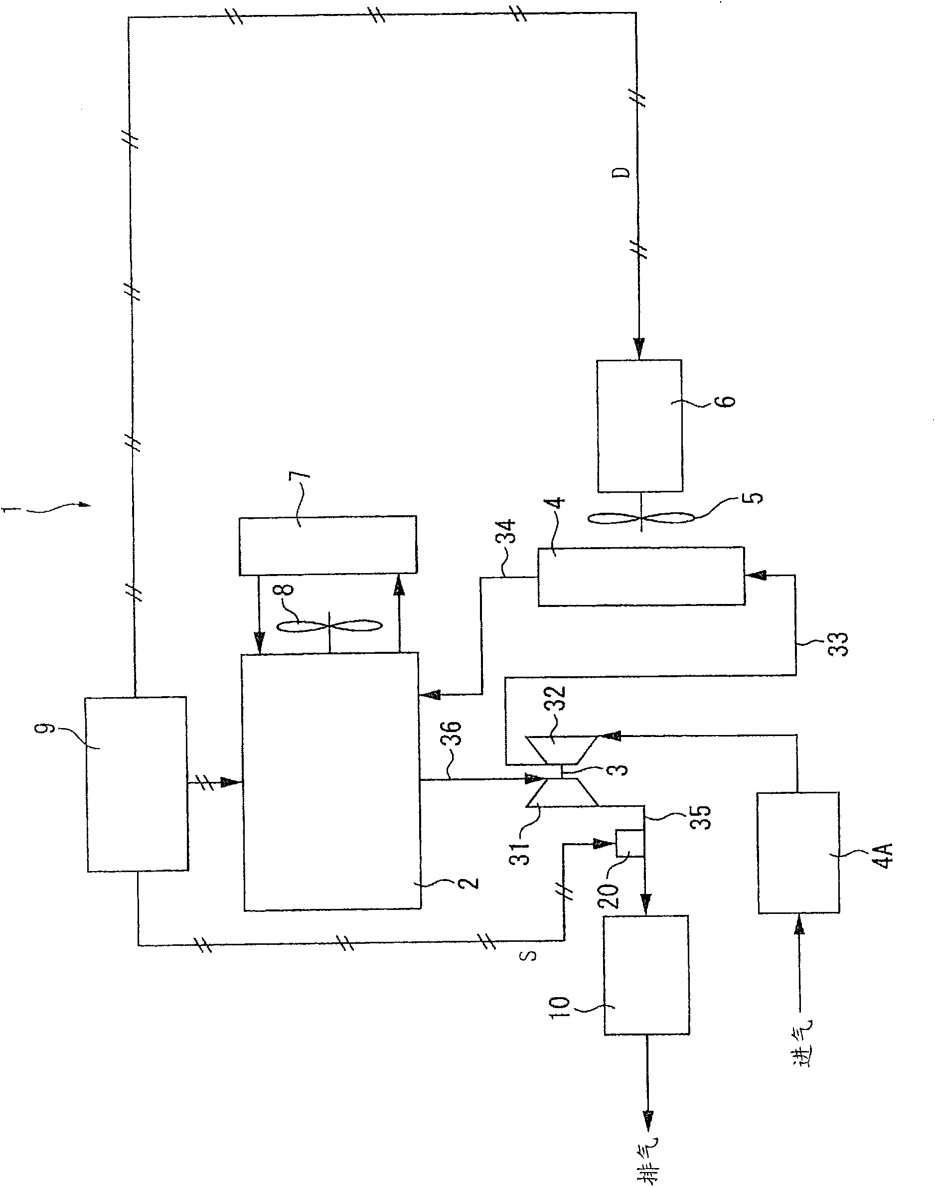
[0062] figure 1 It is a block diagram showing the general configuration of the exhaust purification system 1 according to the first embodiment of the present invention. The exhaust purification system 1 is a system for capturing PM contained in exhaust gas from an engine 2 which is an internal combustion engine, and includes a PM filtering device 10 .

[0063] Here, the engine 2 in the present embodiment is assumed to be a diesel engine. An exhaust turbocharger 3 , which is a supercharger, is attached to the engine 2 via a not-shown exhaust branch pipe. The exhaust turbocharger 3 is composed of a turbine 31 driven by exhaust gas from the engine 2 and a compressor 32 rotating together with the turbine 31 , and the aftercooler 4 is connected to an intake outlet of the compressor 32 through an intake pipe 33 .

[0064] The aftercooler 4 is connected to the engine 2 via an...

no. 2 approach 〕

[0101] In the second embodiment of the present invention, as Image 6 As shown, there is a big difference from the first embodiment in that a rotation speed change determination mechanism 28 is provided in the fan rotation control unit 21 . The rotational speed change determining means 28 determines whether to lower the rotational speed of the cooling fan 5 in the forced regeneration mode.

[0102] Specifically, based on Figure 7 The flow chart of the figure shows that the rotation speed change determining means 28 is as follows: Based on the detection signal from the outside air temperature sensor not shown in the figure, the outside air temperature T is monitored. air , the outside air temperature T air It is compared with a preset temperature ( S12 ), which is a limit temperature at which the durability of the engine 2 may decrease due to forced regeneration fan control.

[0103] When the outside air temperature T air When the limit temperature is reached, the rotation...

no. 3 approach 〕

[0108] exist Figure 8 The third embodiment shown is largely different from the first and second embodiments in that the aftercooler 4 and the radiator 7 are cooled by the cooling air from the cooling fan 5 driven by the driving device 6 . And, in this third embodiment, although the cooling fan 8 driven by the engine 2 is not provided ( figure 1), but the cooling fan 8 can be provided in the same manner as the first method. Other structures, control methods, etc. are the same as those of the first and second embodiments.

[0109] In such a structure, by implementing the same control as in the first and second embodiments, that is, when the soot filter 13 is being regenerated, the rotation speed of the cooling fan 5 is reduced in the forced regeneration mode to raise the intake air temperature, and further The effect similar to that of the first embodiment can be obtained by raising the exhaust gas temperature.

[0110] Moreover, in this embodiment, since the layout is such ...


PUM


Abstract

The invention provides an exhaust gas purifying system for an internal combustion engine and a soot filter regenerating method. An exhaust gas purifying system (1) for an engine (2) is provided with a soot filter in a PM filter device (10) for capturing PM contained in exhaust gas; a regeneration execution determining means in a control device (9), determining whether or not the soot filter is to be regenerated; an air-cooled after cooler (4) for cooling intake air supercharged by an exhaust turbine supercharger (3); a cooling fan (5) for supplying cooling air to the after cooler (4); and a fan speed control means for forcible regeneration, provided in the control device (9) and reducing the speed of the cooling fan (5) when the regeneration execution determining means determines that the soot filter is to be regenerated.

Description

technical field [0001] The present invention relates to an exhaust purification system of an internal combustion engine and a method for regenerating a soot filter, in particular to a regeneration technique for a soot filter that captures PM (particulate matter). Background technique [0002] Conventionally, as a technique for regenerating a soot filter used in an exhaust purification system of an internal combustion engine such as a diesel engine, a technique of performing post injection (post injection) is known. Post-injection refers to fuel injection that is additionally performed separately from normal fuel injection of the engine. By using the oxidation catalyst provided upstream of the soot filter, the post-injected fuel is oxidized to generate heat, the temperature of the exhaust gas flowing into the soot filter is raised, and the PM accumulated in the soot filter is self-ignited by the exhaust gas, thereby Regenerates the soot filter. [0003] In this case, during...

Claims


Application Information

Patent Timeline
Patent Type & Authority Applications(China)
IPC IPC(8): F01N3/02B01D53/94F01N3/20F01N3/24F01N3/36F02D41/04B01D46/42
CPCB01D46/46B01D53/944B01D53/9495B01D53/96B01D2258/012B01D2279/30F01N3/0253F01N9/002F01N2560/06F01N2560/08F01N2560/14F01P7/04F01P2025/44F02B29/0431F02B29/0493F02B37/00F02D41/024F02D41/029F01N13/0097Y02T10/12Y02T10/40B01D46/66
Inventor 小泽吾道小栗秀夫
Owner KOMATSU LTD
Why Eureka
Try Eureka