Controllable coolant pump

A coolant pump, adjustable technology, applied in pump, pump control, pump device, etc., can solve the problems of dynamic performance damage, high processing and assembly costs

Inactive Publication Date: 2011-05-04
NIDEC GPM GMBH
View PDF8 Cites 8 Cited by
  • Summary
  • Abstract
  • Description
  • Claims
  • Application Information

AI Technical Summary

Problems solved by technology

[0018] However, the disadvantage is that, since most of the functional parts of the above-mentioned solutions cannot be standardized, the production and assembly costs of the constructions proposed in DE 10 2005 004 315 B4 and in DE 10 2005 062 200 B3 are still very high, because f

Method used


Image

  • Controllable coolant pump
  • Controllable coolant pump
  • Controllable coolant pump

Examples


Embodiment Construction

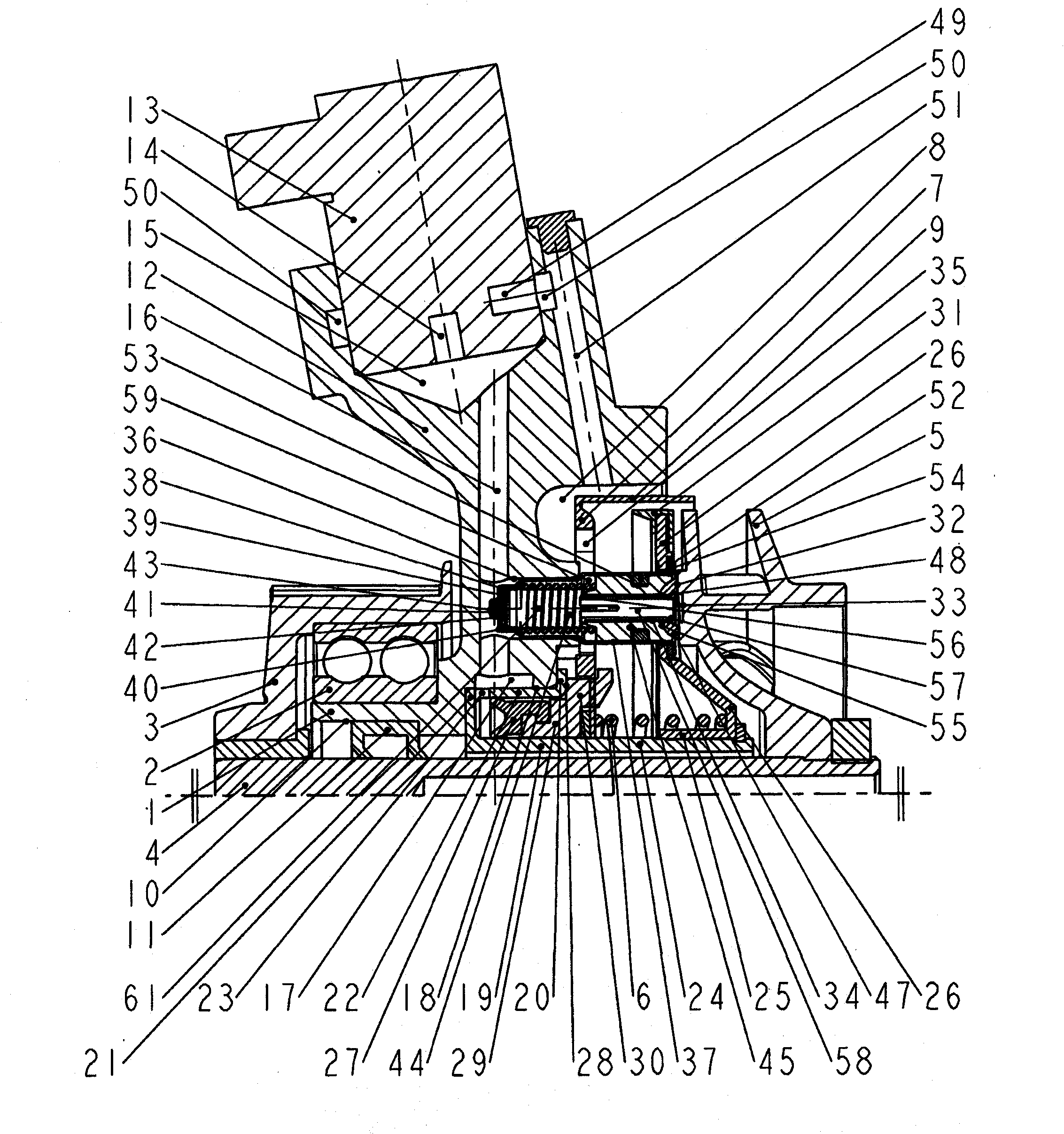
[0036] figure 1 In the form of a side sectional view, the adjustable coolant pump according to the present invention with a slit filter in the first structure is shown, in which the position of the valve core is in its rear end position (that is, in the "open" "In the working position).

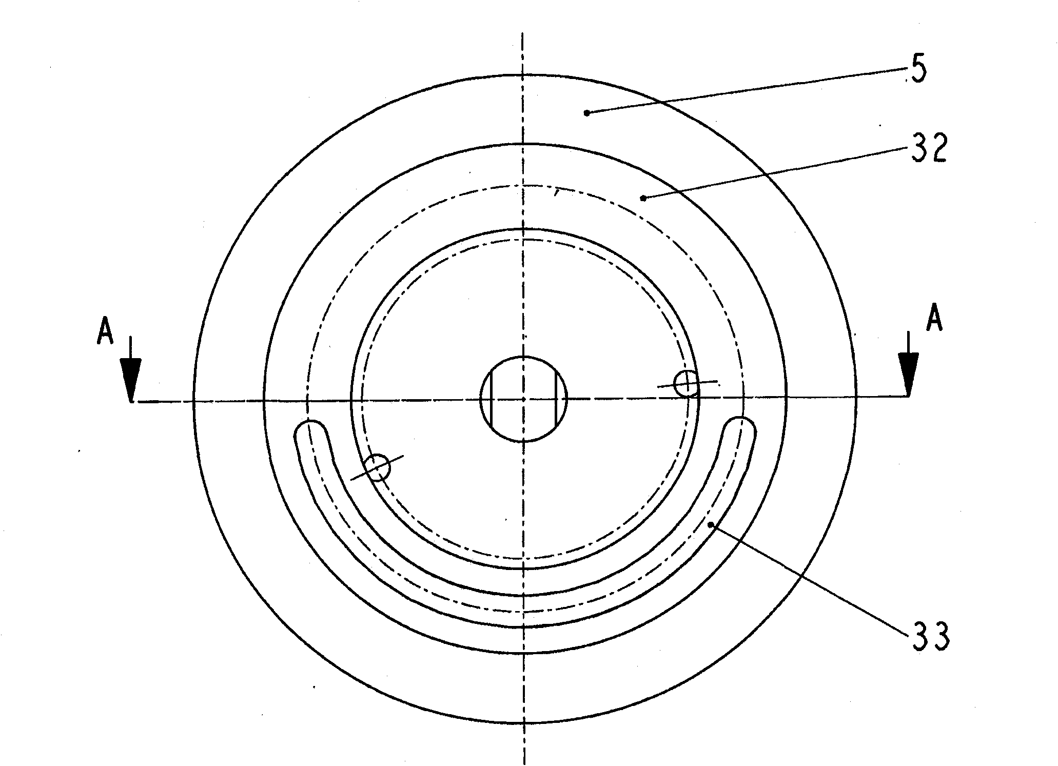
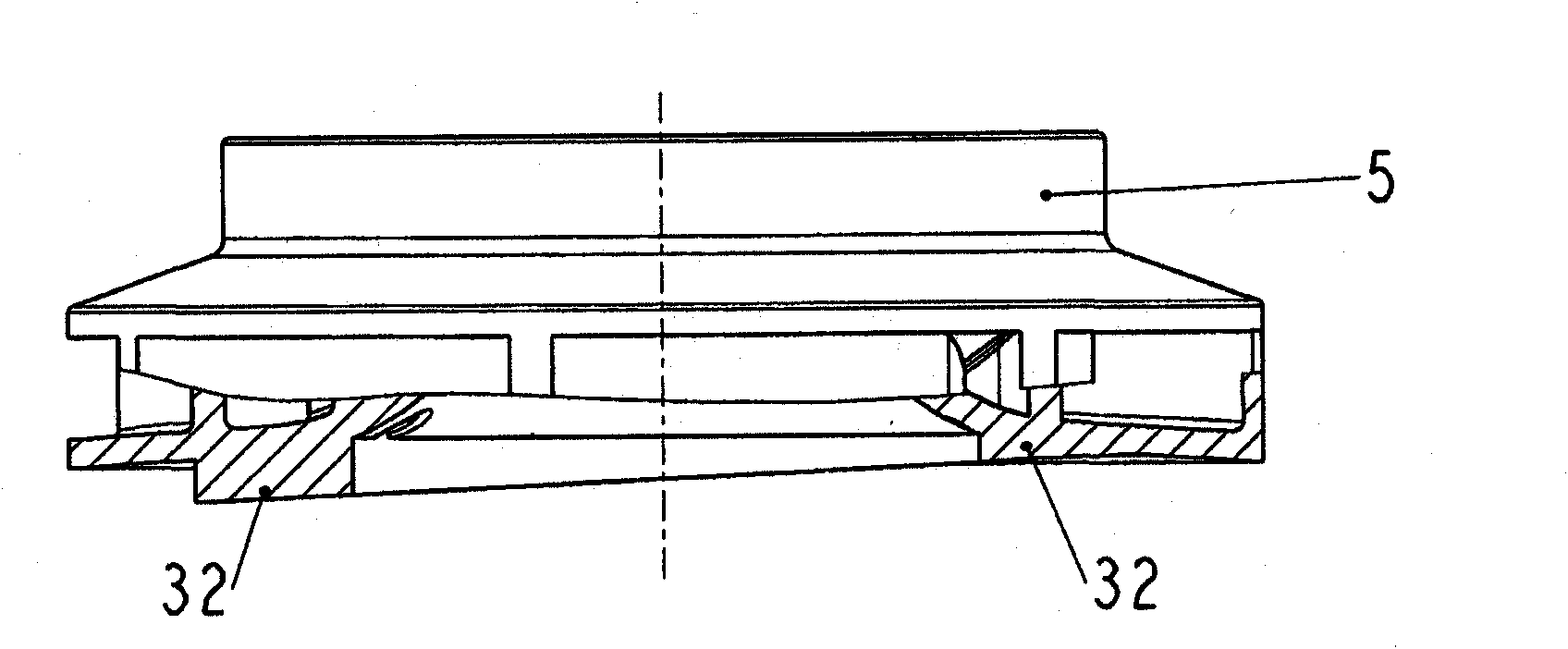
[0037] In this configuration, a pump shaft 4 driven by a pulley 3 with an impeller 5 arranged in a torque-proof manner on the end of the pump shaft 4 on the free-flow side is arranged on a pump housing 1. 2 in.

[0038] In addition, a pressure-operated spool with a rear wall 7 and an outer sleeve 9 that variably covers the outflow region of the impeller 5 and spring-loaded by a return spring 6 is arranged in the pump interior 8.

[0039] In the pump housing 1, a shaft sealing ring 11 is arranged in a sealing seat 10 between the impeller 5 and the pump bearing 2.

[0040] According to the invention, a working housing 12 is arranged on the pump housing 1, and a solenoid valve 13 with an inlet 14 is ar...


PUM

PropertyMeasurementUnit
Thicknessaaaaaaaaaa

Abstract

The invention relates to a controllable coolant pump. The aim of the invention is to develop a controllable coolant pump (having a gate valve) driven by a belt pulley, allowing significant reduction in both pollutant emissions and frictional losses and fuel consumption over the entire working range of the engine, and allowing reliable actuation of the gate valve with very low drive power, even under unfavorable thermal boundary conditions, such as in proximity of the turbocharger, as well as under very limited installation space, and ensuring continued functioning of the coolant pump (fail-safe) even if the controller fails, and characterized by a very simple, low-cost production and assembly design ''standardized'' for different pump sizes, thereby ensuring continuously high operational reliability at a high volumetric efficiency, and requiring no air-free charging in the factory, and that can be simply and inexpensively integrated in the engine management system. The controllable coolant pump according to the invention, having a gate valve and driven by a belt pulley (3) and having a hydraulically actuated gate valve connected to a ring piston (29) is characterized in that an axial piston pump (61) disposed in the pump housing (1) is driven and ''operated'' by means of a swashplate (32) having a suction groove (33) and disposed on the back side of the flywheel (5), the ''pumped volume flow'' thereof being controlled in a defined manner by means of a solenoid valve (13) such that precise displacement of the hydraulically actuated gate valve is ensured.

Description

Technical field [0001] The invention relates to an adjustable coolant pump driven by a pulley of an internal combustion engine. Background technique [0002] In view of the fact that emissions and fuel consumption are very important in the continuous optimization of internal combustion engines, so that the engine can reach operating temperature as quickly as possible after a low temperature start. [0003] This not only reduces the friction loss to a minimum (the viscosity of the engine oil decreases as the oil temperature increases, and therefore the friction on all oil-lubricated parts), but also the emission value decreases (because until the so-called "start-up temperature" The catalytic converter does not work until the temperature is reached, which significantly affects exhaust emissions), and fuel consumption is also significantly reduced. [0004] A series of tests in the engine development show that "no water flow" or "zero leakage" during the low temperature start period i...

Claims


Application Information

Patent Timeline
IPC IPC(8): F04D15/00F04B23/10
CPCF04B23/106F04B23/14F04D15/0038F05D2270/64F04D13/12
Inventor E·施米特F·帕韦莱克E·盖塞尔D·哈根M·雷克斯豪泽
Owner NIDEC GPM GMBH
Why Eureka
Try Eureka