Light well point drainage construction technology

A construction technology, light well point technology, applied in infrastructure engineering, construction, etc., can solve the problems of large influence range of precipitation, unsteady control, no drop, etc., to reduce the difficulty and cost of hole forming, improve the progress of hole forming, Small effect

Inactive Publication Date: 2011-05-11
惠州市水电建筑工程有限公司
View PDF3 Cites 22 Cited by
  • Summary
  • Abstract
  • Description
  • Claims
  • Application Information

AI Technical Summary

Problems solved by technology

[0004] (1) Due to the use of large apertures, the pore-forming and well-forming equipment is heavy, occupies a large area, is inconvenient to move, and has complex hole and well wall structures, high cost and slow construction
[0005] (2) Due to the complex structure of the well wall, the surroundings are easily blocked by mud skin, and the supply water in the sand layer is extremely unstable, so the water pump is difficult to work stably and is easily damaged
[0006] (3) The funnel effect of single well precipitation is not obvious, and the groundwater level between wells does not drop obviously or basically does not drop, and the expected effect cannot be achieved
[0007] (4) The traditional light well point dewatering construction has poor adaptability, and the same type of water pump cannot adapt to the formation of different water permeability and the change of the water output of the tube well during the pumping process
[0008] (5) There are still two obvious deficiencies in the traditional light-weight well point dewatering construction method: due to the l

Method used


Image

  • Light well point drainage construction technology
  • Light well point drainage construction technology
  • Light well point drainage construction technology

Examples


Embodiment Construction

[0037] The present invention will be further described below in conjunction with specific examples, but the specific examples do not limit the present invention in any way.

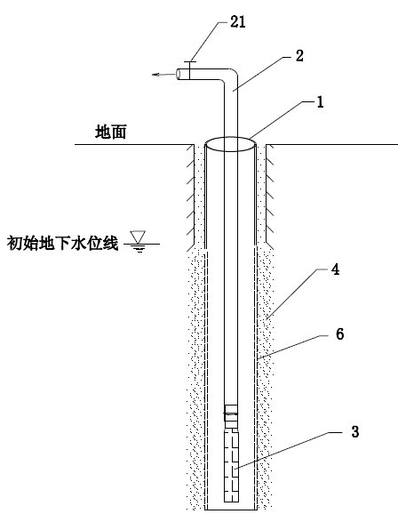
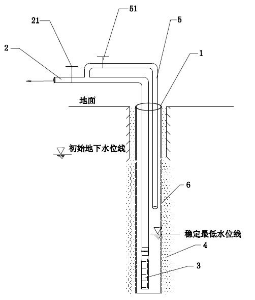
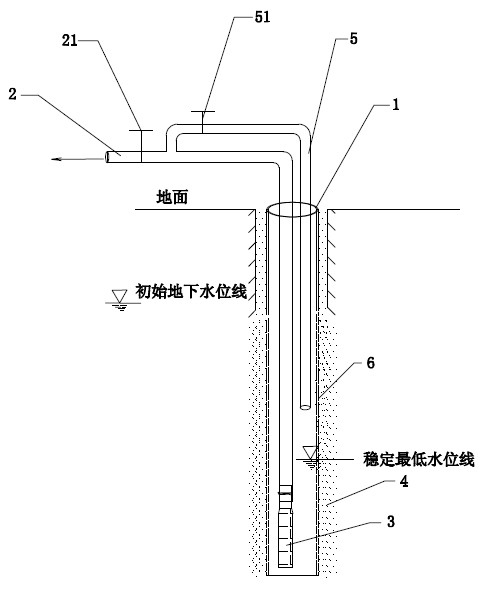
[0038] Huizhou Xunliao Coastal Highway Project is located on the coast of Daya Bay in Xunliao Town, Huidong County, Guangdong Province. It is a section of X210 Provincial Highway and is a key project for the development of Xunliao Coastal Resort and Leisure Area.

[0039] The municipal drainage culvert of this project is arranged longitudinally on the left side of the road, and the excavation depth of the foundation pit is about 5-6m. The foundation surface is located in the silt, medium sand and gravel sand layers deposited by the Quaternary marine-terrestrial interaction facies. The buried water level is relatively shallow (only 1.2m), with good water-rich properties and high permeability coefficient. The distance between the foundation pit and the water surface boundary of the sea is 100-150m; engineer...


PUM

PropertyMeasurementUnit
Diameteraaaaaaaaaa

Abstract

The invention discloses a light well point drainage construction technology. In the technology, a hole is drilled on a slurry protective wall by a conventional geological drilling rig, a filter pipe is arranged in the wall to form a tube well; high pressure water is adopted to inject and flush the inside of the filter pipe to destroy the slurry structure layer of the protective wall and ensure a filter layer is automatically formed on the periphery of the filter pipe; a water outlet pipe the front end of which is provided with a submersible pump is arranged in the filter pipe; and finally, the submersible pump is started to realize well point drainage, wherein the diameter of the tube well is less than or equal to 200mm, the distance among the tube wells is between 3 and 10m; and a return water pipe is arranged on the water outlet pipe. The light well point drainage construction technology provided by the invention is improved on the basis of the traditional light well point drainage; by adjusting the drilling machinery, the diameter and distance of the tube wells and combining the tube well forming technology with the flow rate adjustment controlled water pumping technology, great drainage effect can be obtained, the movement is convenient, the construction speed is fast, the influence range is small, energy sources are saved, and the assembly and disassembly are convenient; and light well point drainage construction technology provided by the invention is suitable for foundation pit excavation of medium and small depth natural sloping in weak to strong water permeable soil layers.

Description

technical field [0001] The invention relates to a light well point dewatering technology for foundation pits, in particular to an improved light well point dewatering construction technology. Background technique [0002] my country's coastal tourism industry has developed rapidly in recent years, and the construction of municipal and water conservancy infrastructure in coastal areas is increasing. Often these projects are located in the silt, medium sand, and gravel sand layers deposited by the Quaternary marine-terrestrial interfacial deposits, which have strong water-rich properties. Water permeability, poor engineering properties. The excavation of the foundation pit involves the drainage of the foundation pit. [0003] The traditional light well point dewatering construction method is a common method in foundation pit excavation dewatering and drainage measures, because most of the excavation depth is within 8 meters. If the dewatering is successful, the foundation pit ...

Claims


Application Information

Patent Timeline
IPC IPC(8): E02D19/20
Inventor 苏学灵陈璐张建平李胜黄绍派李海忠何玉玺龙洪甘瑾
Owner 惠州市水电建筑工程有限公司
Why Eureka
Try Eureka