Processing method for cover plate of mobile terminal equipment

A mobile terminal and processing method technology, applied in the direction of stone processing tools, stone processing equipment, fine working devices, etc., can solve the problems of difficulty in demolding, difficult processing, and high difficulty, so as to improve processing efficiency and yield, and reduce cost. Hole difficulty, the effect of reducing inefficiency

Inactive Publication Date: 2020-06-05
苏州赛万玉山智能科技有限公司
View PDF7 Cites 0 Cited by
  • Summary
  • Abstract
  • Description
  • Claims
  • Application Information

AI Technical Summary

Problems solved by technology

[0005] However, due to the characteristics of sapphire's own texture, it is impossible to form a curved frame or a full curved surface by hot bending, and it is also difficult to achieve 2.5 / 3D cold processing, and the cost is extremely high
[0006] The ceramic back cover is usually sintered by single-piece injection molding, and then cold-processed to achieve a 2.5 / 3D frame or full-curved surface effect. However, due to the high hardness and toughness of ceramics, it is difficult to process, and diamond tools are generally used for CNC machine processing. Finally, Polishing with diamond polishing fluid is difficult, low yield, and high cost
In addition, the ceramic injection method cannot achieve complex structures, such as undercuts and overhang structures, and the ceramic injection method cannot be demoulded without a draft angle; moreover, the structure with a high aspect ratio is difficult to withdraw from the mold after injection molding, or sintering is prone to deformation Or shrinkage and other defects, the yield is low
In order to prevent thermal deformation during the molding and sintering process, the rough blank of the ceramic back cover usually has a large machining allowance, and the camera hole and fingerprint recognition hole cannot be reserved. Since the ceramic material is very difficult to process, this adds a lot to the subsequent cold processing. difficulty and high cost

Method used


Image

  • Processing method for cover plate of mobile terminal equipment
  • Processing method for cover plate of mobile terminal equipment
  • Processing method for cover plate of mobile terminal equipment

Examples


Embodiment Construction

[0050] Objects, advantages and features of the present invention will be illustrated and explained by the following non-limiting description of preferred embodiments. These embodiments are only typical examples of applying the technical solutions of the present invention, and all technical solutions formed by adopting equivalent replacements or equivalent transformations fall within the protection scope of the present invention.

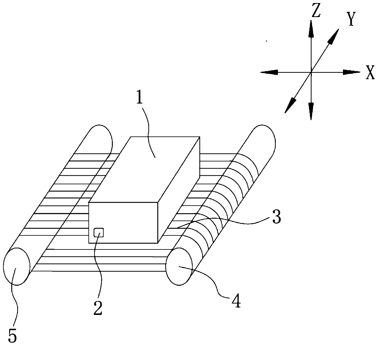
[0051] In the description of the scheme, it should be noted that the terms "center", "upper", "lower", "left", "right", "front", "rear", "vertical", "horizontal", " The orientation or positional relationship indicated by "inner", "outer", etc. is based on the orientation or positional relationship shown in the drawings, and is only for the convenience of description and simplification of description, rather than indicating or implying that the device or element referred to must have a specific orientation , constructed and operated in a particular or...


PUM

PropertyMeasurementUnit
diameteraaaaaaaaaa

Abstract

The invention discloses a processing method for a cover plate of mobile terminal equipment. The processing method comprises the following steps of S1, providing a square brick blank to be processed, the square brick blank is provided with at least one through hole of which the axis is perpendicular to one surface of the square brick blank; S2; enabling a face where a ring formed by a diamond wirein an enclosed mode is located is perpendicular to the axis of the through hole; driving the diamond wire to rotate, and enabling the diamond wire or the square brick blank to feed in the first direction at least; and cutting the square brick blank to obtain at least one cover plate. The method is ingenious in design; by adopting the way of forming the hole in advance and then forming a piece, thepore-forming stability and reliability are ensured, and the problems of easy break of the piece and low rate of finished products due to the way of forming the piece firstly and then forming the holeare solved effectively; and the processing efficiency and the rate of the finished products are improved greatly.

Description

technical field [0001] The invention relates to the field of processing parts of intelligent terminal equipment, in particular to a processing method for a cover plate of a mobile terminal equipment. Background technique [0002] At present, the representative material for the front cover of mobile terminal products such as mobile phones is Corning’s Gorilla Glass. Most of them are processed into 2.5D frames by cold processing or processed into 3D curved frames or full curved surfaces by hot bending. [0003] At present, the protective back covers of representative mobile terminal products are mainly made of glass, ceramics and plastic / plastic materials; plastic / plastic materials are mainly used in low-end products. [0004] And as users pay more and more attention to the appearance of mobile terminals, for some high-end products, more and more non-metallic materials such as glass, ceramics, and sapphire are used as the front cover and the back cover. Especially for some hi...

Claims


Application Information

Patent Timeline
Patent Type & Authority Applications(China)
IPC IPC(8): B28D1/08B28D5/04
CPCB28D1/08B28D5/045
Inventor 万明
Owner 苏州赛万玉山智能科技有限公司
Why Eureka
Try Eureka