Automobile-used muffler

A technology for mufflers and vehicles, which is applied in the direction of mufflers, machines/engines, engine components, etc. It can solve the problems of reduced engine output power, exhaust gas cannot be discharged smoothly, and exhaust muffler effect is poor, so as to reduce exhaust noise, Effect of reducing soot and toxic gas and speeding up

Inactive Publication Date: 2011-05-11
安星圭 +1
View PDF0 Cites 12 Cited by
  • Summary
  • Abstract
  • Description
  • Claims
  • Application Information

AI Technical Summary

Problems solved by technology

[0005] Therefore, the problem existing in the structure of the current vehicle muffler (5) is that the exhaust gas is subjected to relatively large resistance by the blocking plates (5b, 5d) and the porous pipes (5c, 5e), so the exhaust gas cannot be discharged smoothly and stays inside, which brings a blow to the engine. The load is reduced, so the output power of the engine is reduced, fuel loss occurs, the exhaust noise reduction effect is poor, and the discharge of soot and high-temperature harmful gases causes environmental pollution.

Method used


Image

  • Automobile-used muffler
  • Automobile-used muffler
  • Automobile-used muffler

Examples


Embodiment Construction

[0039] The preferred embodiments of the present invention will be described in detail below in conjunction with the accompanying drawings.

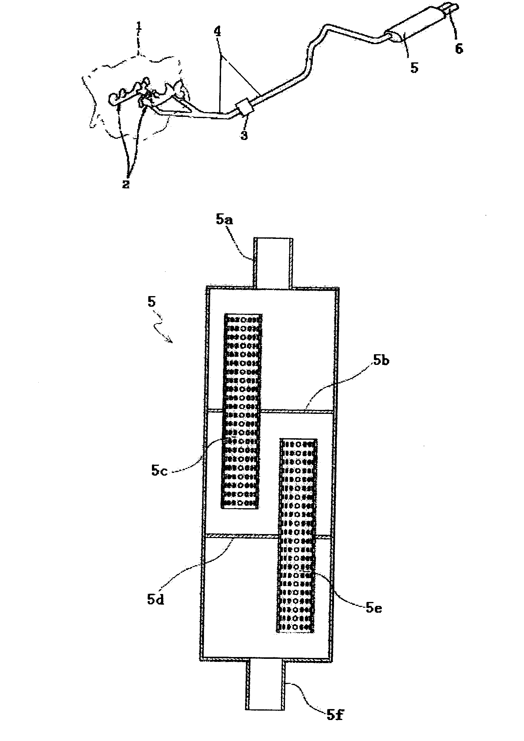
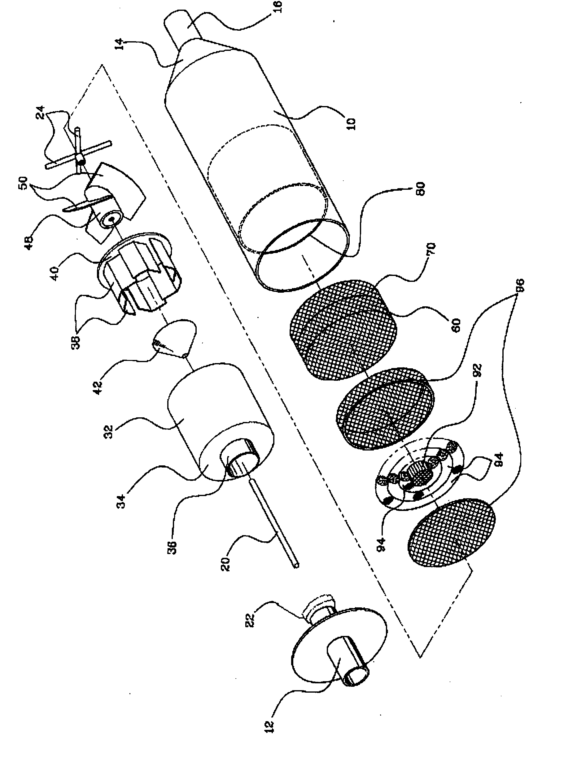
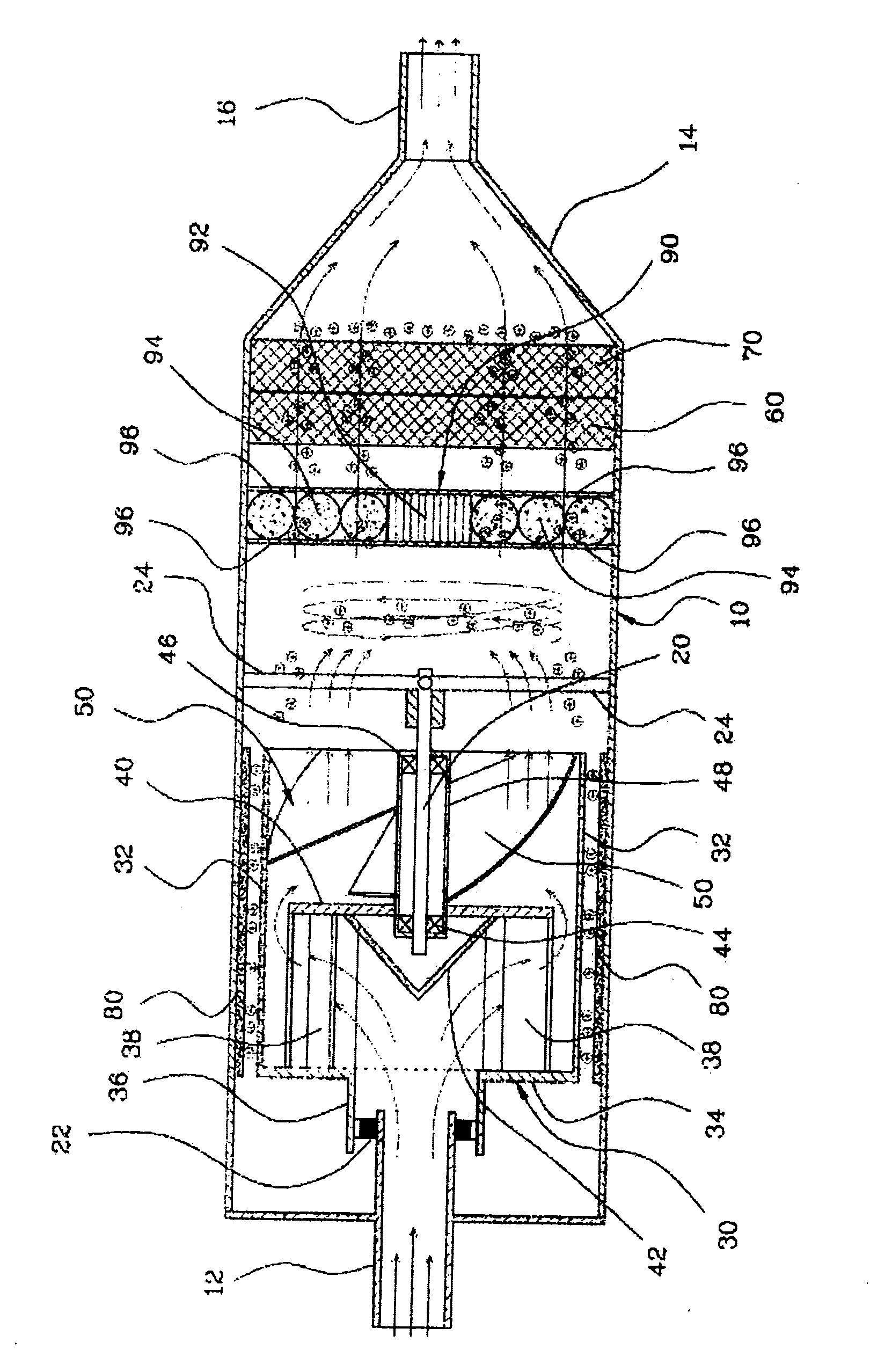
[0040] Figure 2 to Figure 4 An exemplary diagram of the vehicle muffler of the present invention is shown. figure 1 The current muffler shown, figure 2 Shown is an exploded perspective view of the vehicle muffler of the present invention, image 3 Shown is the sectional view of the use state of the vehicle muffler of the present invention, Figure 4 The rotating state of the rotary plate of the vehicle muffler of the present invention is shown.

[0041] As shown in the above figure, the vehicle muffler 100 of the present invention includes: a box body 10 , a fixed shaft 20 , a rotating body 30 , an aluminum mesh 60 , a copper mesh 70 , a static electricity generating part 80 , and a cleaning part 90 .

[0042] The box body 10 is a cylindrical structure with an internal space. One end of the box body 10 is connected to the tubular ai...


PUM


Abstract

An automobile-used muffler comprises a box body, a fixing shaft, a rotator, a bearing box and a slide plate; one end of the box body is connected with a tubular air inlet pipe; a first bearing is arranged on the tubular air inlet pipe, and an inclined part is arranged at the other end; a tubular air outlet pipe is connected to the tail end of the inclined part; a second bearing is arranged at one end of the fixing shaft, and a support part is arranged at the other end and is connected with the inner wall of the box body; the rotator comprises a rotating pipe and a connecting part; the connecting part is connected with the connecting pipe; the air inlet pipe is connected with the connecting pipe through the first bearing; rotating plates are arranged on the inner side of the connecting part; a padding plate is connected to the tail ends of the plurality of rotating plates; a hole is formed in the center of the padding plate, and a conical diverting plate is arranged on the padding plate; the bearing box connected to the middle of the inner side of the padding plate; and the slide plate is connected to the outer wall of the bearing box. After passing the guide plate, tail gas flowing in from the air inlet pipe collides with the diverting plate, so that the direction of the tail gas is adjusted, then the tail gas collides with the rotating plates, and after that, the tail gas passes the slide plate to drive the slide plate to rotate. By adopting the invention, the noise can be decreased, the soot and toxic gas can be reduced, and the oil consumption can be lowered.

Description

technical field [0001] The invention is a device for controlling exhaust gas and noise of automobiles, which is characterized in reducing exhaust noise, reducing harmful exhaust gas, improving engine power and saving fuel. Background technique [0002] Generally, the exhaust device of an automobile is a device that discharges exhaust gas after combustion in an engine to the outside. like figure 1 As shown, the exhaust device includes: an exhaust manifold (2), which collects the exhaust gas discharged from each cylinder of the automobile; a catalytic converter (3), which purifies harmful gases and soot in the exhaust gas; an exhaust pipe (4), which discharges the exhaust gas Exhaust to air; muffler (5) to reduce exhaust noise. [0003] The exhaust path of the exhaust gas is described in detail as follows. The exhaust gas produced in each cylinder of the engine (1) is aggregated together through the exhaust manifold (2). When these exhaust gases pass through the catalytic co...

Claims


Application Information

Patent Timeline
Patent Type & Authority Applications(China)
IPC IPC(8): F01N1/18F01N1/10F01N3/01F01N3/035
Inventor 安星圭
Owner 安星圭
Why Eureka
Try Eureka