Two-stroke photo-thermal engine

An engine, photothermal technology, applied in the energy field

Inactive Publication Date: 2011-05-11
张德胜
View PDF5 Cites 3 Cited by
  • Summary
  • Abstract
  • Description
  • Claims
  • Application Information

AI Technical Summary

Problems solved by technology

At present, there have been examples of Stirling engines installed at the focus of sunlight to generate electricity, but due to the above-mentioned shortcomings of Stirling engines, they have not been promoted and popularized in the utilization of solar energy.

Method used


Image

  • Two-stroke photo-thermal engine
  • Two-stroke photo-thermal engine
  • Two-stroke photo-thermal engine

Examples


Embodiment Construction

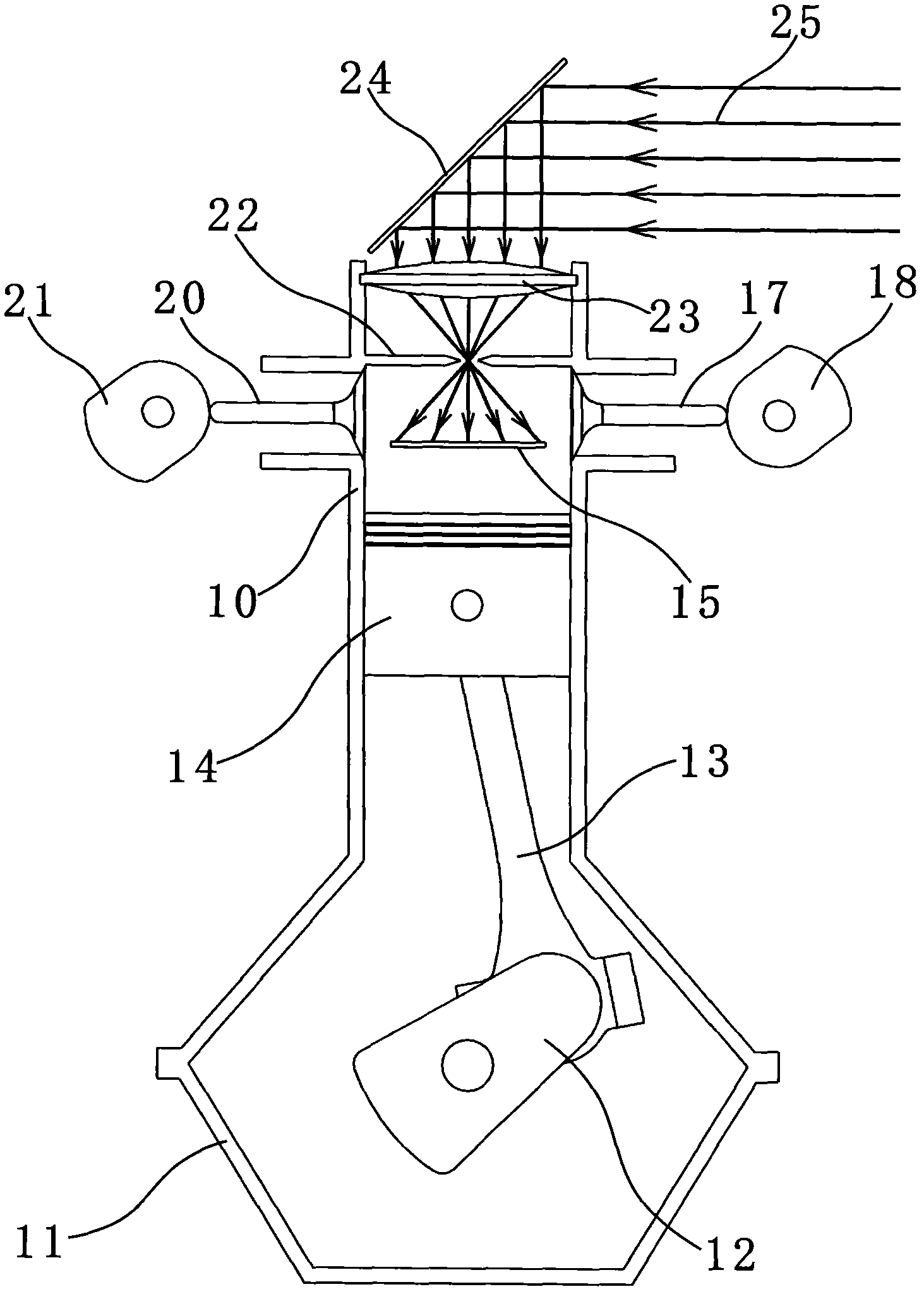
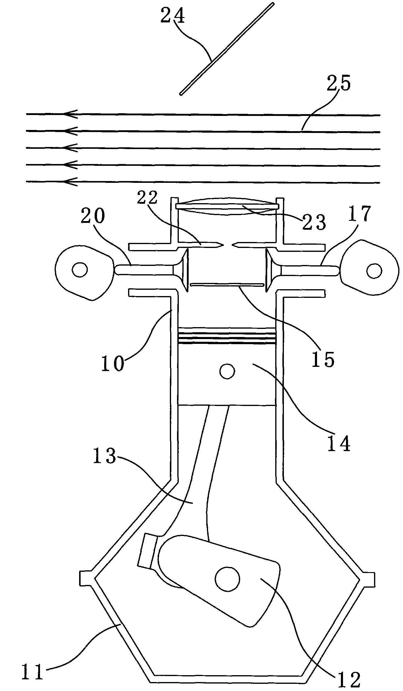
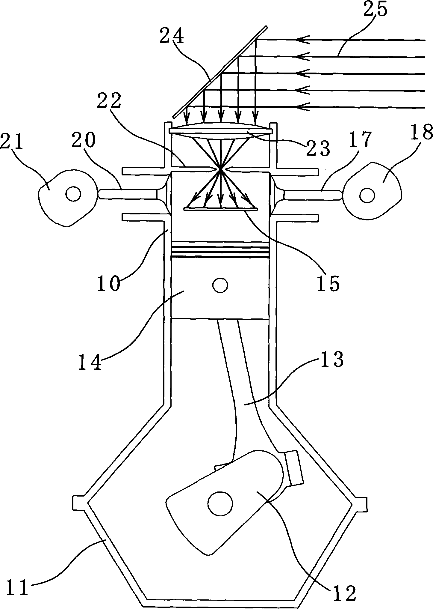
[0023] Such as figure 1 Shown, the present invention is a kind of two-stroke photothermal engine, and it comprises cylinder 10, crankcase 11, crankshaft 12, connecting rod 13, piston 14, photothermal converter 15, intake valve 17, intake valve cam 18, Exhaust valve 20 , exhaust valve cam 21 , sunshield 22 , converging lens 23 , plane reflector 24 . Wherein the piston 14 is installed in the cylinder 10 and can move up and down along the cylinder 10; the crankshaft 12 is installed in the crankcase 11, and the crankshaft 12 is connected with the piston 14 through the connecting rod 13.

[0024] The crankshaft 12 is coupled and driven with the intake cam 18 and the exhaust cam 21 through known mechanical techniques. When the crankshaft 12 rotates, it drives the intake valve cam 18 to control the movement of the intake valve 17, and drives the exhaust valve cam 21 to control the movement of the exhaust valve 20.

[0025] The converging lens 23 is installed on the top of the cylin...


PUM


Abstract

The invention discloses a two-stroke photo-thermal engine which is an engine device for converting the energy of parallel light beams into mechanical energy. The engine provided by the invention comprises a cylinder, a crank case, a crank, a connecting rod, a piston, a photo-thermal converter, an air intake valve, an air exhaust valve, a light hood, a convergent lens, a planar mirror and the like, wherein the photo-thermal converter is positioned in the cylinder; the planar mirror is arranged outside the cylinder and can move downwards along the axis of the cylinder; and parallel light beams are reflected to the convergent lens and scattered to the photo-thermal converter after passing through a small hole in the center of the light hood. The temperature of the photo-thermal converter is increased after light energy is absorbed, a gas working medium in a compression cavity is heated, and the gas working medium is expanded after being heated, so that the piston is pushed to do work, and the mechanical energy is output through the crank, thereby realizing the purpose of outputting the mechanical energy on the premise of not combusting fossil energy. The engine provided by the invention has the advantages of low cost, no gaseous pollutant emission, low noise and no pollution to the environment, is easy to manufacture, and utilizes the parallel light beams as an energy source instead of fossil fuel.

Description

technical field [0001] The invention relates to the field of energy technology, in particular to a non-polluting engine device for converting the energy of parallel light beams into mechanical energy. Background technique [0002] An engine, also known as an engine, is a machine that converts one form of energy into another, more useful form of energy, usually chemical energy into mechanical energy. Looking back at the history of engine generation and development, it has experienced two development stages of external combustion engine and internal combustion engine. [0003] The so-called external combustion engine means that its fuel is burned outside the engine, and the engine converts the heat energy generated by this combustion into kinetic energy. The steam engine improved by Watt is a typical external combustion engine. When it is heated into a large amount of water vapor, high pressure is generated, and then this high pressure drives the machine to do work, thus comp...

Claims


Application Information

Patent Timeline
Patent Type & Authority Applications(China)
IPC IPC(8): F03G6/06F01B29/08F24J2/08F24S23/30
CPCY02E10/46
Inventor 张德胜
Owner 张德胜
Why Eureka
Try Eureka