Permanent-magnet motor capable of effectively eliminating slot effect

A permanent magnet motor and permanent magnet technology, which is applied to the static parts of the magnetic circuit, the rotating parts of the magnetic circuit, and the shape/style/structure of the magnetic circuit. Electrical performance and other issues, to achieve uniform distribution of cogging magnetic field, reduce yoke reluctance, and low processing costs

Inactive Publication Date: 2011-05-11
TIANJIN SANTROLL ELECTRIC SCI & TECH
View PDF11 Cites 12 Cited by
  • Summary
  • Abstract
  • Description
  • Claims
  • Application Information

AI Technical Summary

Problems solved by technology

[0009] The air gap magnetic density has a great influence on the basic performance of the motor. For high-performance and high-torque motors, it is generally not advisable to reduce the air gap magnetic density. The torque output by the motor will be greatly reduced. Increasing the air gap length will reduce the power density of the motor. , both of which result in underefficiency
[0010] 4. Segmented dislocation of chute, oblique pole or magnetic pole
[0012] The above method shows that in the motor with standard structure, when the basic structure remains unchanged, only changing the geometric dimension parameters and electromagnetic parameters of the magnetic system will have a certain effect on reducing the cogging effect, but the basic electrical performance will not be affected excessively. The effect of reducing the cogging effect is also restricted and cannot fully meet the requirements of the motor. For this reason, some more effective methods must be adopted

Method used


Image

  • Permanent-magnet motor capable of effectively eliminating slot effect
  • Permanent-magnet motor capable of effectively eliminating slot effect
  • Permanent-magnet motor capable of effectively eliminating slot effect

Examples


Embodiment Construction

[0026] Below in conjunction with accompanying drawing, the present invention is described in further detail:

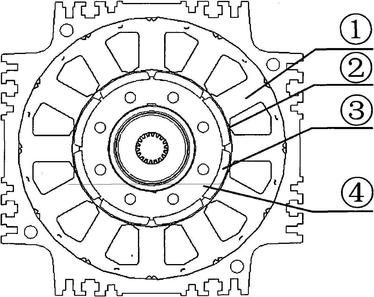
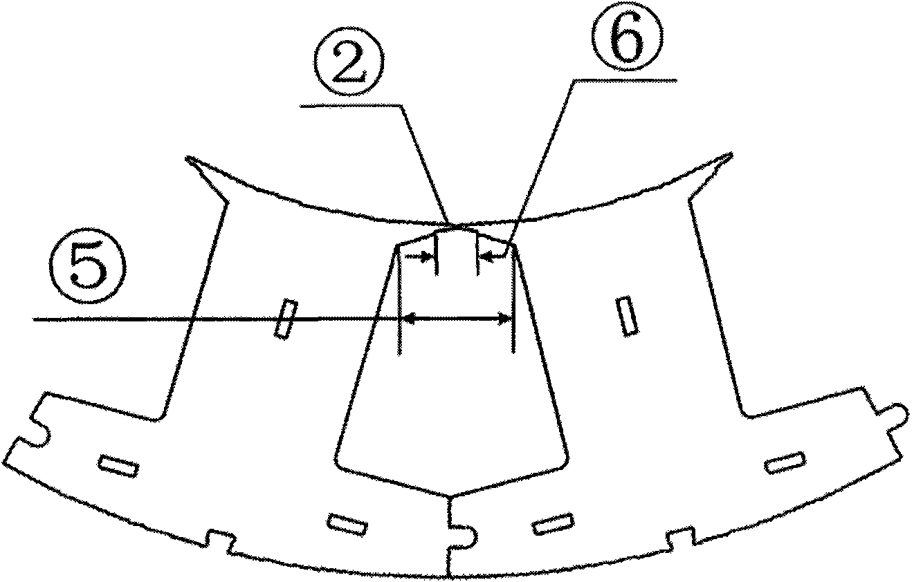
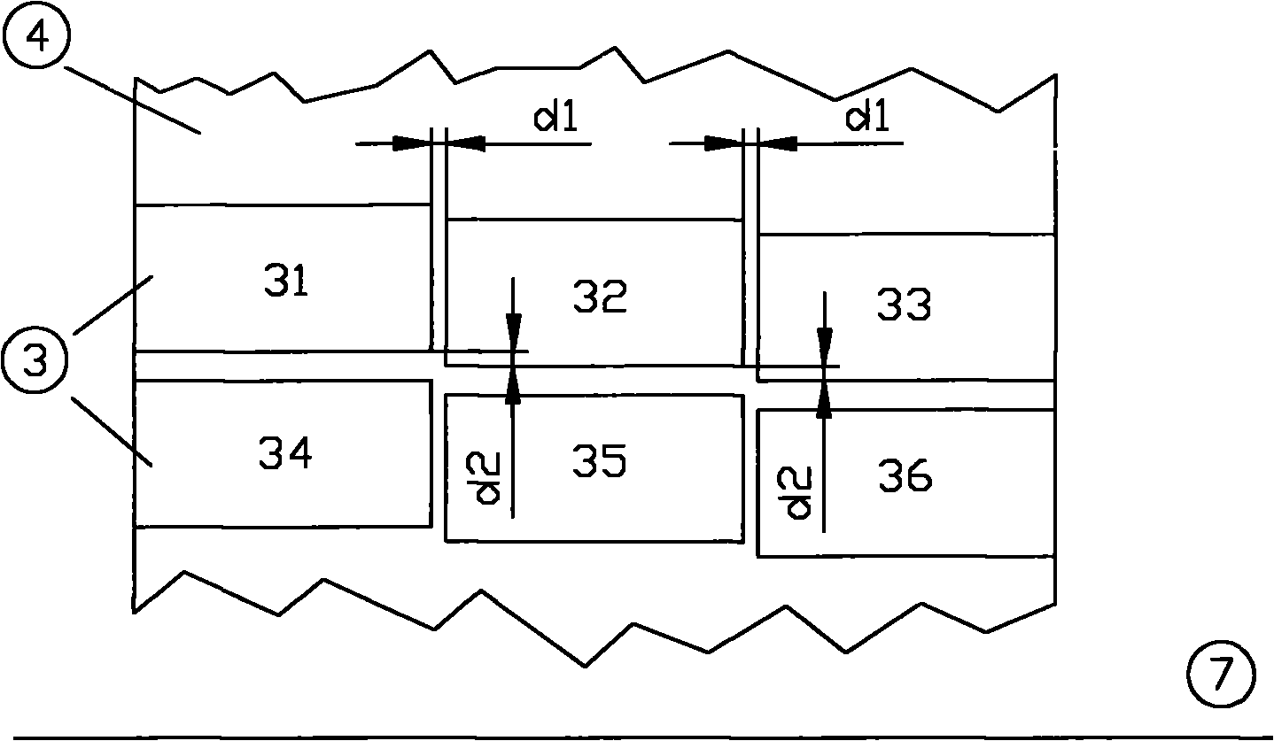
[0027] Such as Figure 1-4 Shown: ① is the stator, ② is the tip of the shoe, ③ is the permanent magnet, ④ is the rotor, ⑤ is the tooth groove, and ⑥ is the notch.

[0028] see figure 1 , is a structural schematic diagram of the permanent magnet motor of the present invention. The permanent magnet motor in this embodiment has 8 poles, and the surface of the permanent magnet ③ is attached to the surface of the rotor ④. The stator of the permanent magnet motor is composed of 12 stator blocks ①, and 12 stators The pieces ① are interlocked together to form a circular outer stator, and the boot tips ② of two adjacent stators are in close contact.

[0029] see figure 2 , is an enlarged schematic diagram of the stator part of the permanent magnet motor of the present invention. Two adjacent stators are firmly spliced ​​through the semicircular grooves on both sides of the...


PUM


Abstract

The invention discloses a set of motor equipment, and aims to provide a permanent magnet motor capable of effectively eliminating a slot effect. The permanent magnet motor adopts the structure that a rotor of the permanent magnet motor is a surface-mount permanent magnet, a stator of the permanent magnet motor adopts a split structure, boot tips are arranged at tooth boots of stator splits, the boot tips of two adjacent stator splits in the circumferential direction are closely contacted with each other and barely have clearance therebetween, notches are formed at the contact parts of the boot tips of the stator tooth boots of the permanent magnet motor, the permanent magnet takes the shape of an eccentric equant tile, the permanent magnet is segmented in the axial direction, the segments of the permanent magnet are placed at intervals, the homopolar permanent magnet segments are sequentially arranged in a malposed manner in the same circumferential direction, and the total malposition distance is the width of a slot. In the permanent-magnet motor provided by the invention, a specific structural combination is adopted to effectively eliminate the slot effect of the permanent magnet motor. The permanent magnet motor provided by the invention has simple manufacturing technology and lower manufacturing cost.

Description

technical field [0001] The invention relates to the technical field of motors, in particular to a permanent magnet motor with a cogging elimination structure. Background technique [0002] The cogging effect of the permanent magnet motor refers to the cogging torque, which is generated in the circumferential direction by the interaction between the permanent magnet magnetic field of the rotor and the cogging structure of the stator core, that is, the rotor of the permanent magnet motor has a The tendency to align the stator in a particular direction, whereby this tendency produces an oscillating torque, independent of the stator current, which always tries to position the rotor in some stable position, this tendency will cause the motor Torque ripple and noise during operation. In variable speed drives, when the torque frequency coincides with the mechanical resonance frequency of the stator or rotor, the vibration and noise generated by the cogging torque will be amplified...

Claims


Application Information

Patent Timeline
Patent Type & Authority Applications(China)
IPC IPC(8): H02K1/14H02K1/27
Inventor 刘延海孔昭松
Owner TIANJIN SANTROLL ELECTRIC SCI & TECH
Why Eureka
Try Eureka