Single-shaft mortar and high-viscosity fluid stirrer for axial turbulent flow pattern multi-wire cutting machine

A multi-wire cutting machine and agitator technology, which is applied to mixers with rotating agitation devices, mixers, liquid and solid mixing, etc., can solve the problems of agitator stuck, cost increase, etc., achieve flexible use and operation, prevent The effect of crushing and low input cost

Inactive Publication Date: 2011-05-18
XIAN HUAJING ELECTRONICS TECH
View PDF6 Cites 13 Cited by
  • Summary
  • Abstract
  • Description
  • Claims
  • Application Information

AI Technical Summary

Problems solved by technology

In the actual production process, in order to increase the production output of the multi-wire cutting machine, it is necessary to install multiple mortar mixing tanks, which puts forward new requirements for factory buildings, and various costs will increase accordingly
[0003] In addition, in the chemical industry, daily necessities industry, mining industry and other industrial fields, there is also an urgent

Method used


Image

  • Single-shaft mortar and high-viscosity fluid stirrer for axial turbulent flow pattern multi-wire cutting machine
  • Single-shaft mortar and high-viscosity fluid stirrer for axial turbulent flow pattern multi-wire cutting machine
  • Single-shaft mortar and high-viscosity fluid stirrer for axial turbulent flow pattern multi-wire cutting machine

Examples


Example Embodiment

[0032] Example 1

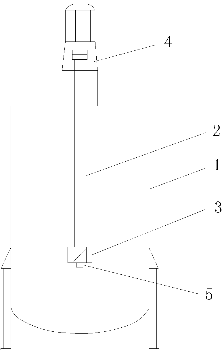
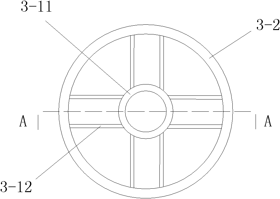
[0033] Such as figure 1 , figure 2 , image 3 and Figure 4 As shown, the present invention includes a mixing shaft 2 coaxially installed in the mixing tank body 1, a mixing assembly 3 that continuously rotates with the mixing shaft 2 and uniformly mixing materials in the mixing tank body 1, and a mixing shaft 2 installed on the mixing shaft 2. A driving mechanism above and driving the stirring shaft 2 to continuously rotate. The drive mechanism and the stirring shaft 2 are connected in transmission through a transmission mechanism. The stirring assembly 3 is coaxially installed at the bottom end of the stirring shaft 2. The mixing assembly 3 includes an impeller 3-1 that carries animal materials along the inner wall of the mixing tank body 1 from the bottom of the tank gradually upward or gradually downwards from the upper surface of the material, and the material makes a spiral motion while limiting the flow direction of the material to The short guide tube...

Example Embodiment

[0049] Example 2

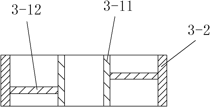
[0050] In this embodiment, the difference from embodiment 1 is: an oval-headed stirring tank with a diameter of Φ1000mm and a height of 1200mm is used, the power of the driving motor is 4KW and the rotation speed is 1500rpm, the effective length of the stirring shaft 2 is 840mm and its diameter is Φ50mm, the outer diameter of the short guide tube 3-2 is Φ180mm and its wall thickness is 5mm, the outer diameter of the coupling sleeve 3-11 is Φ55mm and its height is 50mm, the wall thickness of the coupling sleeve 3-11 is 5mm, the blade The installation angle is 45°, the vertical height of the blade 3-12 is 50mm and its thickness is 3mm, and the connecting shaft sleeve 3-11 and the stirring shaft 2 are connected in a threaded manner. In actual use, the blades 3-12 can also adopt arc-shaped blades with a radius of curvature of 500 mm. In actual use, after putting in 800 liters of cutting fluid at a time, then put in 800 kg of silicon carbide at a time, cover the up...

Example Embodiment

[0051] Example 3

[0052] In this embodiment, the difference from embodiment 2 is: the effective length of the stirring shaft 2 is 480mm and its diameter is Φ30mm, the radius of the short draft tube 3-2 is Φ150mm and its wall thickness is 5mm, and the shaft sleeve 3-11 The outer diameter is Φ35mm and its height is 50mm, the wall thickness of the coupling sleeve 3-11 is 5mm, the blade installation angle is 20°, the vertical height of the blade 3-12 is 50mm and its thickness is 5mm, and the coupling sleeve 3 -11 and the stirring shaft 2 are connected by key. In actual use, the blades 3-12 can also be arc-shaped blades with a radius of curvature of 35mm. The stirring speed of the stirring shaft 2 is 600 rpm. In this embodiment, the structure, connection relationship and working principle of the remaining parts are the same as those in the second embodiment.


PUM

PropertyMeasurementUnit
Radiusaaaaaaaaaa
Radius of curvatureaaaaaaaaaa
Radiusaaaaaaaaaa

Abstract

The invention discloses a single-shaft mortar and high-viscosity fluid stirrer for an axial turbulent flow pattern multi-wire cutting machine, comprising a stirring shaft, a stirring assembly and a driving mechanism, wherein the stirring assembly comprises impellers and short flow diversion tubes, the impellers are used for driving a material to move up or down in an axial and spiral mode along the inner wall of a pot body of a stirring pot, the short flow diversion tubes are used for restricting the material flow direction to an axial movement along the axis of the stirring shaft when the material moves up or down in the axial and spiral mode, the impellers and the short flow division tubes are assembled into the stirring assembly which drives the material needed to be mixed and stirred to do an axial turbulent flow motion during stirring, the impellers are coaxially installed at the bottom end of the stirring shaft, the short flow division tubes are coaxially and fixedly sleeved at the outer sides of the impellers, and the stirring speed of the stirring shaft is 600-1500rmp. The single-shaft mortar and high-viscosity fluid stirrer has the advantages of simplicity in structure, high stirring capacity, small shearing force, high dispersing power and high effect, and can be used for solving the problem that silicon carbide is broken due to the shearing force during the high-speed stirring of various traditional stirrers. Moreover, a stuck phenomenon is difficult to generate.

Description

technical field [0001] The invention relates to a single-shaft agitator, in particular to a single-shaft agitator for axial turbulent flow type multi-wire cutting machine mortar and high-viscosity fluid. Background technique [0002] The cutting mortar for multi-wire cutting machine is a high liquid-solid ratio of up to 1:0.95, that is, a high-viscosity suspension, and the solid silicon carbide of the suspension must have good dispersion during actual cutting. At the same time, the solid silicon carbide is very uniformly suspended in the cutting fluid to form a cutting mortar. And during the stirring process of the slurry, it is necessary to avoid violent stirring to cause the silicon carbide particles to be sheared and broken to affect their cutting performance. In the traditional mortar mixing tank for multi-wire cutting machine, the agitator is mostly a paddle or frame agitator. During the mixing process, the fluid flow pattern is generally radial movement, and the fluid...

Claims


Application Information

Patent Timeline
IPC IPC(8): B01F7/22B01F7/18B01F3/14B01F27/91B01F23/57
Inventor 杨国农贺鹏杨易穆增涛陈波
Owner XIAN HUAJING ELECTRONICS TECH
Why Eureka
Try Eureka