Method for manufacturing pole coil

A technology of a magnetic pole coil and a manufacturing method, which is applied in the directions of manufacturing tools, auxiliary devices, auxiliary welding equipment, etc., can solve the problems of increased short circuit between turns of the magnetic pole coil, burning of copper compacts and induction coils, and uneven dissolution of silver solder pieces, etc. The effect of reducing unit cost, good welding joint quality, and expanding the design size range

Inactive Publication Date: 2011-05-25
TIANJIN TIRNFR HEAVY HYDROELECTRIC FRCILITY CO LTD
View PDF4 Cites 5 Cited by
  • Summary
  • Abstract
  • Description
  • Claims
  • Application Information

AI Technical Summary

Problems solved by technology

[0003] When the welding specification of the copper bar exceeds the range of 8×65, the copper bar cannot be placed in the center of the induction coil due to the large cross-section of the copper bar, and the clamping device cannot accurately position the copper bar welding and cause displacement, which is easy to cause Due to the incorrect position of the clamping force of the water-cooled U-shaped copper briquette, the induction coil inductively heats the welding joints and soldering pieces of the two copper bars, which is prone to uneven dissolution of the silver soldering piece and false welding, which may easily cause the magnetic pole coil turns after the hot pressing is completed. If the short circuit increases, the copper pressing block and the induction coil will be burned, so the clamping device of the gripper should be adjusted to meet the production needs.

Method used


Image

  • Method for manufacturing pole coil
  • Method for manufacturing pole coil

Examples


Embodiment Construction

[0015] In order to further understand the invention content, characteristics and effects of the present invention, the following examples are given, and detailed descriptions are as follows in conjunction with the accompanying drawings:

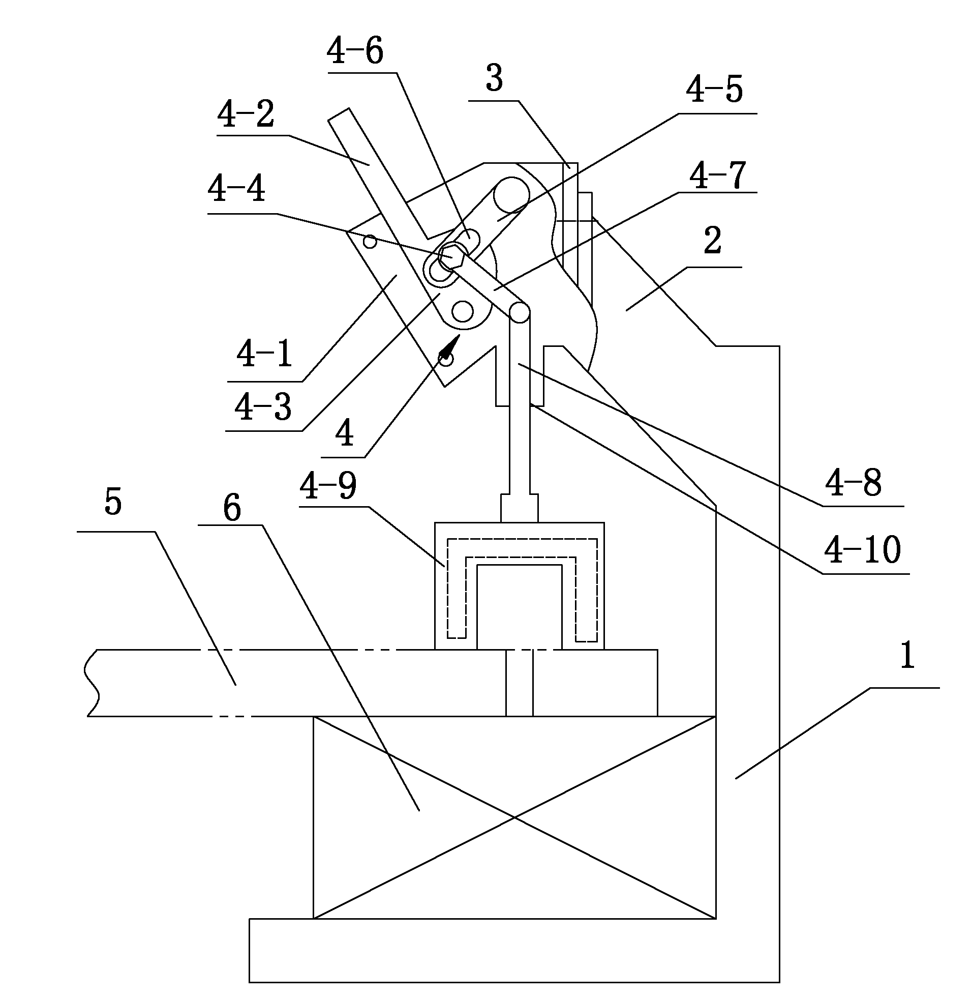
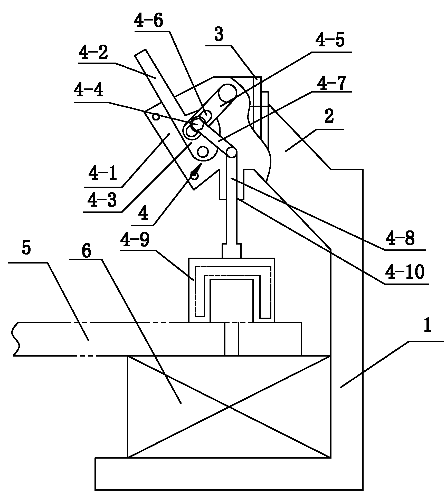
[0016] see figure 1 ,

[0017] A method of manufacturing a magnetic pole coil:

[0018] 1. First, install the tightening and positioning device according to claim 1 on the brazing machine, and adjust its position to detect whether the power supply is turned on and whether the cooling system is operating normally;

[0019] 2. Place the solder piece between the welding ports of the two copper bars, and discharge the copper to be welded on the center of the induction coil. Adjust the adjustment plate horizontally to ensure that the U-shaped indenter is facing the center of the induction coil. After adjustment, manipulate the movable handle Press the U-shaped pressure head on the two copper bars to be welded;

[0020] 3. After adjusting the po...


PUM


Abstract

The invention relates to a method for manufacturing a pole coil, which is characterized by comprising the following steps of: (1) firstly, installing a clamping / positioning device on a brazing machine; (2) then, installing a soldering lug between craters of two copper bars, and operating a handle so as to enable a pressure head to be pressed against and then welded on the copper bars; (3) adjusting the position of the pressure head so as to keep the pressing force to be in a tendency of an equilibrium state; and (4) finally, electrifying a high-frequency induction power of the high-frequency brazing machine so as to enable an inductance coil to induce and heat the craters and the soldering lug of the copper bars, and keeping the pressing force for three to five seconds, then after the soldering lug is solidified, starting up the clamping / positioning device so as to complete the manufacturing of the pole coil. The method provided by the invention has the advantages that the defects of turn-to-turn faults and the like caused by uneven dissolved silver soldering lugs and poor soldering existing in the process of welding the copper bars are overcome, and the efficiency and quality of welding are improved; after the crater is processed by a pressing mechanism, the quality of the crater is good; meanwhile, the method also has the advantages of improving the utilization rate of materials, expanding the range of design size, reducing the unit cost, achieving the purpose of accurately machining workpieces, and effectively solving the problem of machining quality of a large four-head welding pole coil.

Description

technical field [0001] The invention relates to the technical field of welding equipment auxiliary devices, in particular to a method for manufacturing a magnetic pole coil. Background technique [0002] At present, in the special welding equipment used by our company, if the welding specification of the copper bar is within the range of 8×65, the induction coil and the clamping mechanism of the hand gripper are fixed on the L-shaped curved plate bracket of the slide plate, and the copper bar is placed on the induction coil. At the center of the circle, after placing the solder piece between the welding ports of the two copper bars, before welding, press the two copper bars with a water-cooled U-shaped copper briquetting block, and clamp the copper bars with a manual gripper to weld them Accurate positioning, timely cooling of copper briquettes and circulating water system to prevent overheating of copper briquettes. [0003] When the welding specification of the copper bar...

Claims


Application Information

Patent Timeline
Patent Type & Authority Applications(China)
IPC IPC(8): B23K1/002B23K37/053
Inventor 路春玲
Owner TIANJIN TIRNFR HEAVY HYDROELECTRIC FRCILITY CO LTD
Why Eureka
Try Eureka