Large-angle, continuous and high-resolution beam deflection scanning device based on liquid crystal optical phased array and scanning method
A technology of liquid crystal optics and beam deflection, applied in optics, optical components, nonlinear optics, etc., to achieve cost-saving and volume-reducing effects
- Summary
- Abstract
- Description
- Claims
- Application Information
AI Technical Summary
Problems solved by technology
Method used
Image
Examples
specific Embodiment approach 1
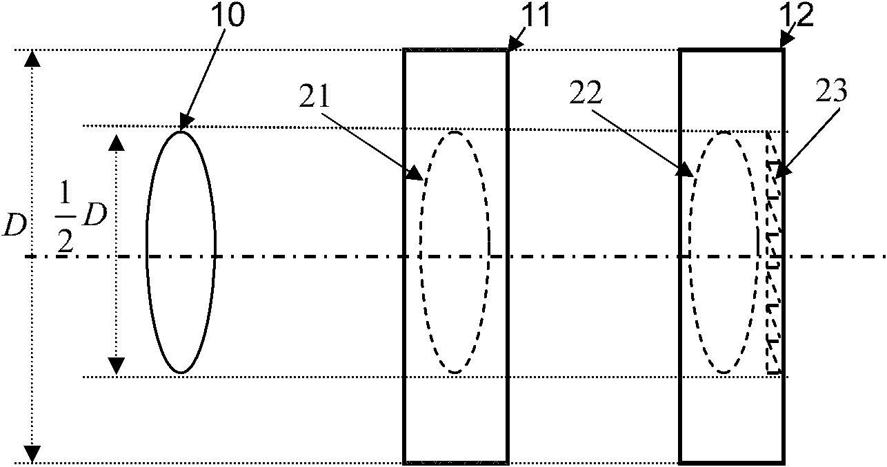
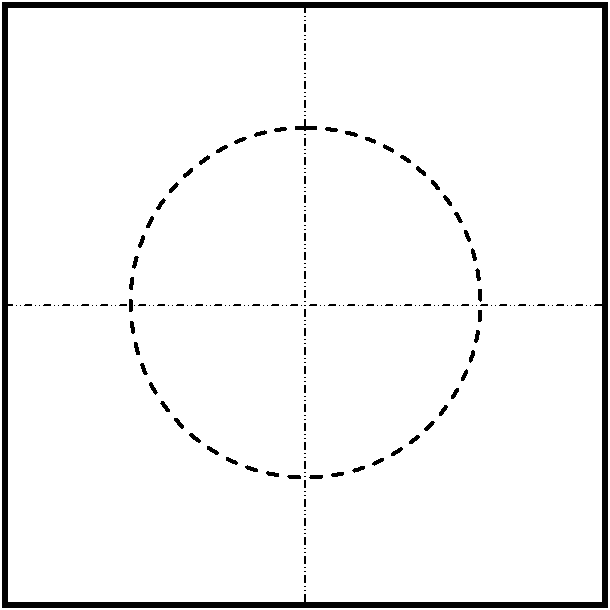
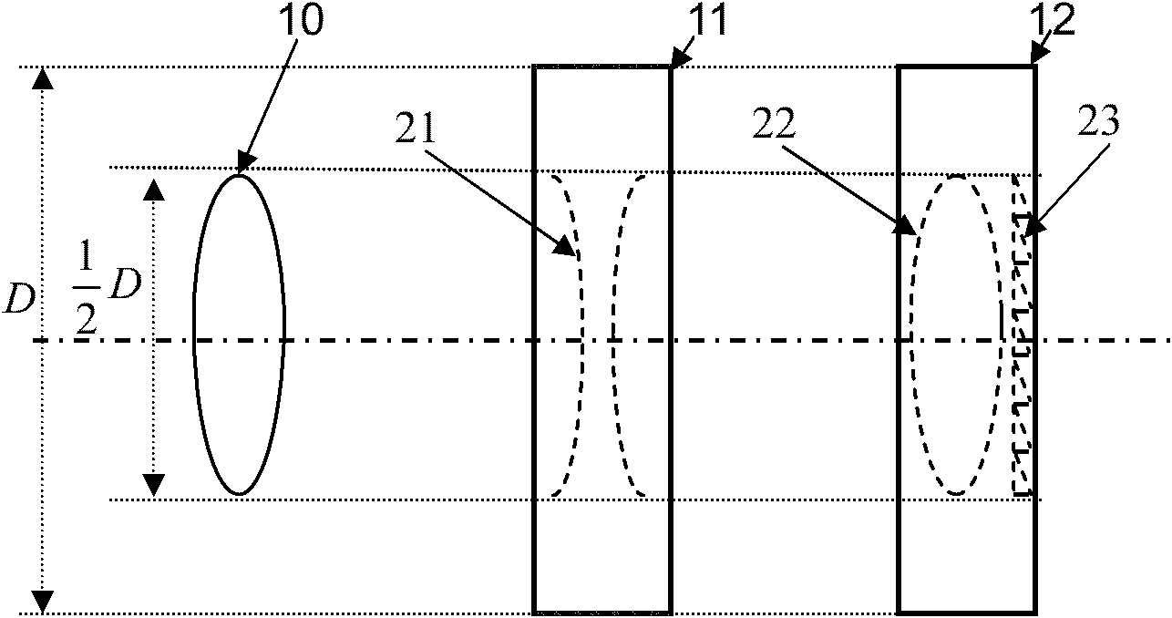
[0027] Specific implementation mode one: combine Figure 1 to Figure 12 Describe this embodiment, this embodiment is a large-angle continuous high-resolution beam deflection scanning device based on a liquid crystal optical phased array. A lens or lens array 10, a first liquid crystal optical phased array 11 and The second liquid crystal optical phased array 12,
[0028] Wherein the first liquid crystal optical phased array 11 and the phase shift unit of the second liquid crystal optical phased array 12 have the same pixel size and the same filling factor, and the first liquid crystal optical phased array 11 produces a first liquid crystal lens or a liquid crystal lens array 21 , the second liquid crystal optical phased array 12 produces a second liquid crystal lens or liquid crystal lens array 22 and a blazed grating 23 with variable period or variable blaze,
[0029] The lens or lens array 10, the first liquid crystal lens or liquid crystal lens array 21 and the second liquid...
specific Embodiment approach 2
[0040] Specific implementation mode two: combination Figure 1 to Figure 12 Describe this embodiment, the steps of this embodiment are as follows:
[0041] Step 1: first select the lens or lens array 10, then select the first liquid crystal optical phased array 11 that produces the first liquid crystal lens or liquid crystal lens array 21, and generate the second liquid crystal lens or liquid crystal lens array 22 and variable period or variable blaze The second liquid crystal optical phased array 12 of the blazed grating 23, the selected first liquid crystal optical phased array 11 and each phase shift unit of the second liquid crystal optical phased array 12 have the same pixel size and the same fill factor, and A first liquid crystal lens or liquid crystal lens array 21 and a second liquid crystal lens or liquid crystal lens array 22 having the same effective diameter as the lens or lens array 10 can be produced;
[0042] Step 2: Calculate the initial phase diagram of the ...
specific Embodiment approach 3
[0053] Specific implementation mode three: combination Figure 11 and Figure 12 This embodiment is described. The difference between this embodiment and the second specific embodiment is that the initial phase diagram, the initial composite phase diagram, the deflection phase diagram and the deflection composite phase diagram are obtained through a phase function;
[0054] First, the expression of the eccentricity of the first liquid crystal lens or liquid crystal lens array 21 and the second liquid crystal lens or liquid crystal lens array 22 is:
[0055] Δ(x, y)=(Δ(x), Δ(y))=(x·d x ,y·d y )0≤x≤M / 2, 0≤y≤N / 2
[0056] Among them, x, y are the number of moving steps in the X and Y directions respectively; M and N are the number of phase shift units in the X and Y directions of the phased array respectively; d x , d y The size of the phase shift unit of the liquid crystal phased array;
[0057] The phase function of the phase diagram of the first liquid crystal optical pha...
PUM
 Abstract
Description
Claims
Application Information
 - R&D
- Intellectual Property
- Life Sciences
- Materials
- Tech Scout
- Unparalleled Data Quality
- Higher Quality Content
- 60% Fewer Hallucinations
Browse by: Latest US Patents, China's latest patents, Technical Efficacy Thesaurus, Application Domain, Technology Topic, Popular Technical Reports.
© 2025 PatSnap. All rights reserved.Legal|Privacy policy|Modern Slavery Act Transparency Statement|Sitemap|About US| Contact US: help@patsnap.com


