Method for producing silicon-based ceramic core for aircraft engine blade
An aero-engine and ceramic core technology, applied in the field of ceramic cores, can solve problems such as difficult shapes
- Summary
- Abstract
- Description
- Claims
- Application Information
AI Technical Summary
Problems solved by technology
Method used
Image

Examples
preparation example Construction
[0047] The present invention is a kind of preparation method that is applicable to the silicon-based ceramic core that aeroengine blade is used, and it comprises following steps:
[0048] Step 1. Mixing of powder
[0049] Put the fine powder, medium powder and coarse powder of high-purity (mass percentage purity: 99.99%) silicon dioxide by weighing into a polytetrafluoroethylene ball mill tank, and dry-mill for 30 minutes to 60 minutes to obtain a mixed powder;
[0050] Then put the mixed powder into an oven with a temperature of 80°C to 100°C and a drying time of 10min to 30min to obtain a dry mixed powder;
[0051] Dosage: 8-15g of fine powder, 15-30g of medium powder and the rest of coarse powder in 100g of mixed powder;
[0052] The average particle size of the fine powder is 1-5 μm;
[0053] The average particle size of medium powder is 10-25μm;
[0054] The average particle size of the coarse powder is 40-80 μm;
[0055] In the present invention, the mixed powder aft...
Embodiment 1
[0079] Step 1. Mixing of powder
[0080] Put the fine powder, medium powder and coarse powder of high-purity (mass percentage purity: 99.99%) silicon dioxide into a polytetrafluoroethylene ball mill tank, and dry mill for 40 minutes to obtain a mixed powder;
[0081] Then put the mixed powder into an oven with a temperature of 80°C and a drying time of 30 minutes to obtain a dry mixed powder;
[0082] Dosage: 12.5g of fine powder, 25g of medium powder and the rest of coarse powder in 100g of mixed powder;
[0083] The average particle size of the fine powder is 2.7 μm;
[0084] The average particle size of medium powder is 12.44μm;
[0085] The average particle size of coarse powder is 43.09μm;
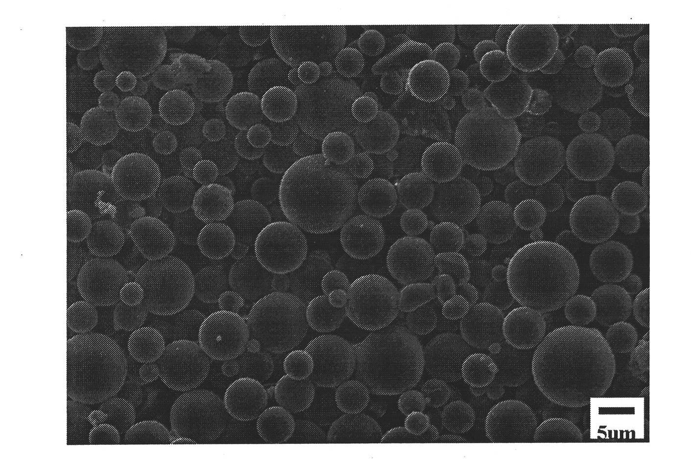
[0086] In the present invention, the appearance of high-purity (mass percentage purity is 99.99%) silica mixed powder is as follows figure 1 As shown, the particles in the figure have a relatively regular spherical structure, which is conducive to improving the fluidity of the sil...
Embodiment 2
[0108] Step 1. Mixing of powder
[0109] Put the fine powder, medium powder and coarse powder of high-purity (mass percentage purity: 99.99%) silicon dioxide into a polytetrafluoroethylene ball mill tank, and dry mill for 30 minutes to obtain a mixed powder;
[0110] Then put the mixed powder into an oven with a temperature of 90°C and a drying time of 15 minutes to obtain a dry mixed powder;
[0111] Dosage: 10g of fine powder, 20g of medium powder and the rest of coarse powder in 100g of mixed powder;
[0112] The average particle size of the fine powder is 4.5 μm;
[0113] The average particle size of medium powder is 20.2μm;
[0114] The average particle size of the coarse powder is 59.8 μm;
[0115] Step 2. Preparation of slurry
[0116] The plasticizer is put into an oil bath temperature and melted in a stirrer with a temperature of 90° C. to obtain the first intermediate; the plasticizer is a mixture of paraffin wax and beeswax, and the mass ratio of paraffin wax to...
PUM
| Property | Measurement | Unit |
|---|---|---|
| particle size | aaaaa | aaaaa |
| particle size | aaaaa | aaaaa |
| particle size | aaaaa | aaaaa |
Abstract
Description
Claims
Application Information
 - R&D
- Intellectual Property
- Life Sciences
- Materials
- Tech Scout
- Unparalleled Data Quality
- Higher Quality Content
- 60% Fewer Hallucinations
Browse by: Latest US Patents, China's latest patents, Technical Efficacy Thesaurus, Application Domain, Technology Topic, Popular Technical Reports.
© 2025 PatSnap. All rights reserved.Legal|Privacy policy|Modern Slavery Act Transparency Statement|Sitemap|About US| Contact US: help@patsnap.com