Method and device for dyeing by utilizing ultrasonic wave and microwave

A dyeing method, ultrasonic technology, applied in the field of dyeing using ultrasonic waves and microwaves and its devices, can solve the problems of low dye utilization rate, affecting dyeing efficiency, and high water consumption, so as to improve dyeing effect, improve dyeing efficiency, and save water resource effect

Inactive Publication Date: 2011-06-01
YANCHENG INST OF IND TECH
View PDF5 Cites 20 Cited by
  • Summary
  • Abstract
  • Description
  • Claims
  • Application Information

AI Technical Summary

Problems solved by technology

[0002] At present, the dyeing method of textiles is mainly by mixing dyes and auxiliary agents in water to form a dye solution of a certain concentration, and dyeing textiles under a certain temperature and pressure. The disadvantage is that the water consumption in the dyeing process is too much , the energy consumption of wastewater treatment is too large, the utilization rate of dyestuffs is low, and the production cost is high, which is not conducive to low-carbon, ecological and environmental protection
At the same time, due to the use of a large number of additives, it is difficult to separate the dyes from the additives, which is not conducive to the recycling of dyes
In recent years, people have developed the use of supercritical CO 2 The method for dyeing textiles, although it has the advantages of no pollution, no need to dry the dyed fabric, save water resources, etc., also has the following deficiencies: one is in the whole dyeing process, in order to keep the CO 2 In the supercritical state, the pressure needs to reach about 7.38MPa. This kind of high pressure state has high requirements on equipment and complicated operation, which is very unsuitable for industrialization.
The second is CO 2 The supercritical state is not easy to maintain, and it is easy to be destroyed and affect its dyeing efficiency
Third, due to CO 2 Due to its non-polar characteristics, it can only dissolve non-polar or low-polar dyes, so the suitable dyes are greatly limited. Generally, disperse dyes are commonly used, and the dyed varieties are very limited.

Method used


Image

  • Method and device for dyeing by utilizing ultrasonic wave and microwave
  • Method and device for dyeing by utilizing ultrasonic wave and microwave

Examples


Embodiment 1

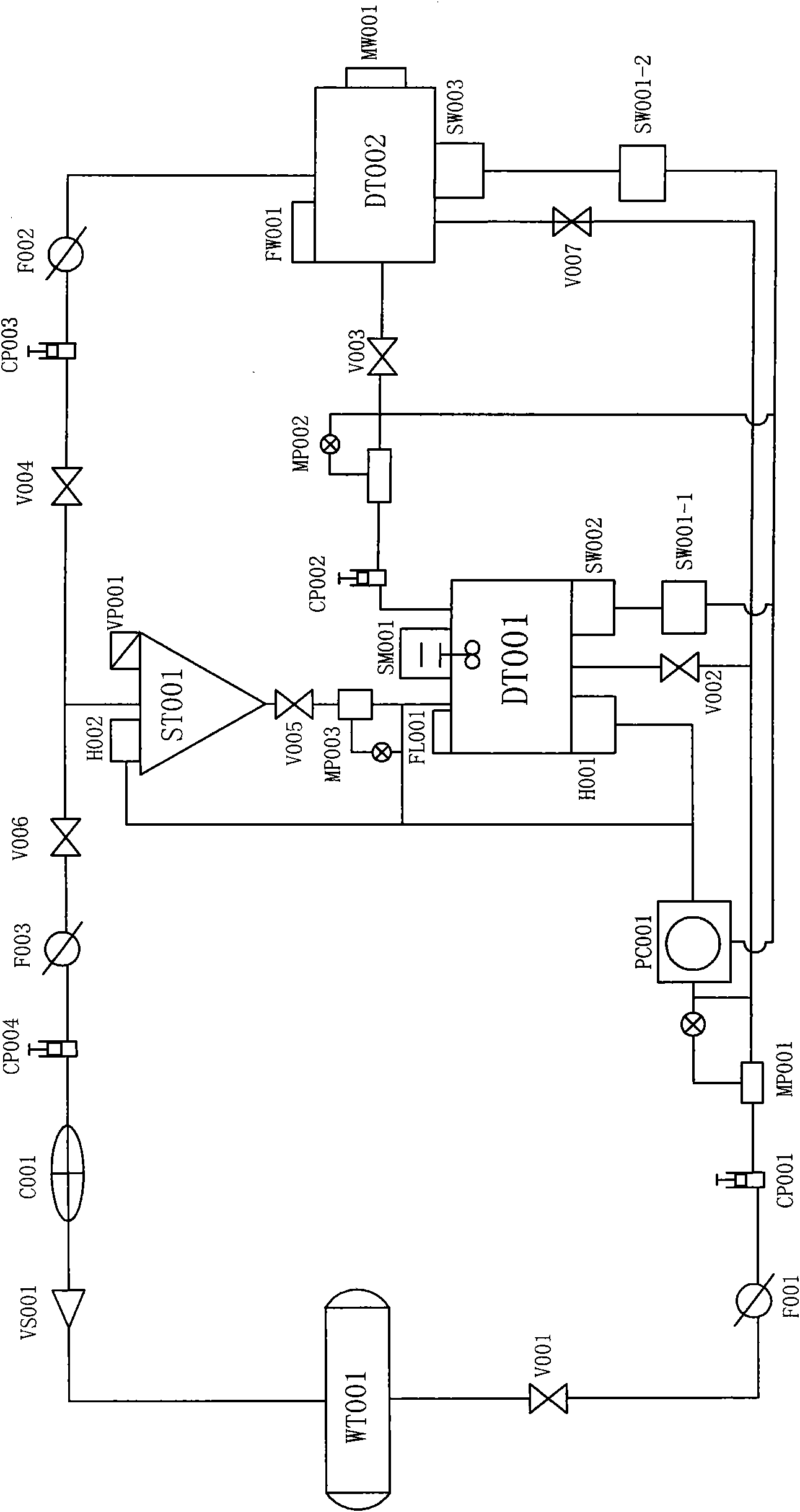
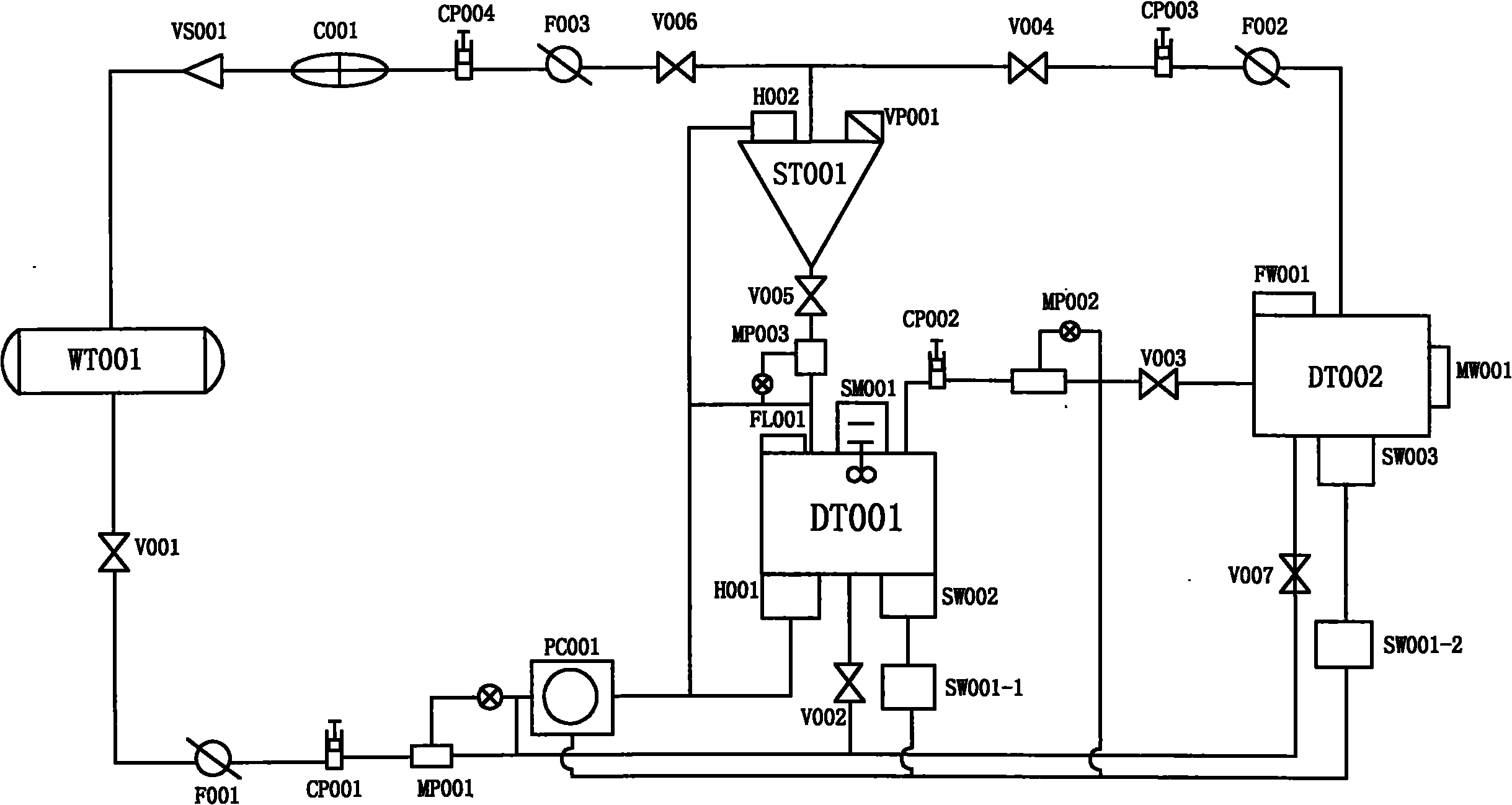
[0022] The dyeing device using ultrasonic waves and microwaves used in the embodiment of the present invention includes a water storage tank WT001, a dye kettle DT001, a dyeing kettle DT002, a separator ST001, an ultrasonic generator SW001-1, an ultrasonic generator SW001-2, and an ultrasonic transducer Device SW001, ultrasonic transducer SW002, microwave generator MW001 and control unit PC001; said water storage tank WT001 passes through the valve V001, filter F001, circulation pump CP001, metering pump MP001 and valve V002 connected in sequence, and is connected with the dye kettle DT001 is connected. Dye kettle DT001 is equipped with heater H001, agitator SM001 and ultrasonic transducer SW001, and dye kettle DT001 is connected to dye kettle DT002 through circulation pump CP002, metering pump MP002 and valve V003 connected in sequence. Dyeing kettle DT002 is equipped with ultrasonic transducer SW002 and microwave generator MW001, ultrasonic transducer SW002 is connected with...

Embodiment 2

[0030] The dyeing device utilizing ultrasonic waves and microwaves adopted in this embodiment is the same as that in Embodiment 1.

[0031] The dyeing method that utilizes ultrasonic wave and microwave described in the embodiment of the invention, for adopting above-mentioned device, be 100 to specification with neutral black S-GL dyestuff S ×80 S / 150×13088″, 5kg silk fabric dyeing as an example:

[0032] 1) Preparation of dye solution, open the valve V001, the water in the water storage tank WT001 is filtered by the filter F001, and then under the action of the circulation pump CP001, the 60L water measured by the metering pump MP001 enters the dye kettle DT001, and passes through the dye kettle DT001 Add 25g of neutral black S-GL dye to the upper discharge port FL001, then close the valves V001 and V002, and the heater H001 will heat the dye kettle DT001 at a constant temperature at a fixed time, and the temperature is 50°C; the stirrer SM001 starts to stir at a constant s...

Embodiment 3

[0038] The dyeing device utilizing ultrasonic waves and microwaves adopted in this embodiment is the same as that in Embodiment 1. The dyeing method utilizing ultrasonic wave and microwave described in the embodiment of the invention, for adopting above-mentioned device, be 80 to specification with disperse blue BGL S ×80 S / 120×10058″, 5kg polyester poplin fabric dyeing as an example:

[0039] 1) Preparation of dye liquor, open the valve V001, the water in the water storage tank WT 001 is filtered by the filter F001, and then under the action of the circulation pump CP001, 100L of water measured by the metering pump MP001 enters the dye kettle DT001, and passes through the dye kettle Add 25g of disperse blue BGL to the discharge port FL001 on DT001, and then close the valves V001 and V002. The heater H001 heats the dye kettle DT001 at a constant temperature at a fixed time, and the temperature is 50°C; the agitator SM001 starts stirring at a constant speed, and the speed is ...


PUM


Abstract

The invention provides a method and device for dyeing by utilizing ultrasonic waves and microwaves. The dyeing device comprises a water storage tank WT001, a dye kettle DT001, a dyeing kettle DT002, a separator ST001, an ultrasonic generator SW001-1, an ultrasonic generator SW001-2, an ultrasonic transducer SW001, an ultrasonic transducer SW002 and a microwave generator MW001. The dyeing method comprises the steps of: preparing dye liquor under the action of ultrasonic waves, dyeing fabric under the action of ultrasonic waves and microwaves, treating the dye liquor after dyeing, and recycling the recovered water and dye. The method and device for dyeing has the following benefits: the dyeing efficiency and the dyeing effect are effectively improved without using assistants, and the dye can be recycled; and simultaneously, the dyeing device has simple structure, is convenient to control, reduces energy consumption and saves water resources.

Description

technical field [0001] The invention relates to a dyeing method and a device thereof, in particular to a dyeing method and a device using ultrasonic waves and microwaves. Background technique [0002] At present, the dyeing method of textiles is mainly to mix dyes and auxiliaries in water to form a dye solution of a certain concentration, and to dye textiles under a certain temperature and pressure. The disadvantage is that the water consumption in the dyeing process is too much , The energy consumption of wastewater treatment is too large, the utilization rate of dyestuff is low, and the production cost is high, which is not conducive to low carbon, ecology and environmental protection. At the same time, due to the use of a large number of auxiliary agents, it is difficult to separate the dye from the auxiliary agent, which is not conducive to the recycling of the dye. In recent years, people have developed the use of supercritical CO 2 The method for dyeing textiles, alt...

Claims


Application Information

Patent Timeline
Patent Type & Authority Applications(China)
IPC IPC(8): D06B13/00D06B23/00D06B23/20
CPCD06B13/00
Inventor 王慧玲周彬
Owner YANCHENG INST OF IND TECH
Why Eureka
Try Eureka