

Joint process for preparing ethylene and synthesis gas by direct conversion of methane
A technology for synthesis gas and methane, which is applied in the chemical industry, sustainable manufacturing/processing, inorganic chemistry, etc., and can solve the problems of complex processes, high manufacturing costs, and large CO2 emissions.
- Summary
- Abstract
- Description
- Claims
- Application Information
AI Technical Summary
Problems solved by technology
Method used
Image

Examples
Embodiment 1
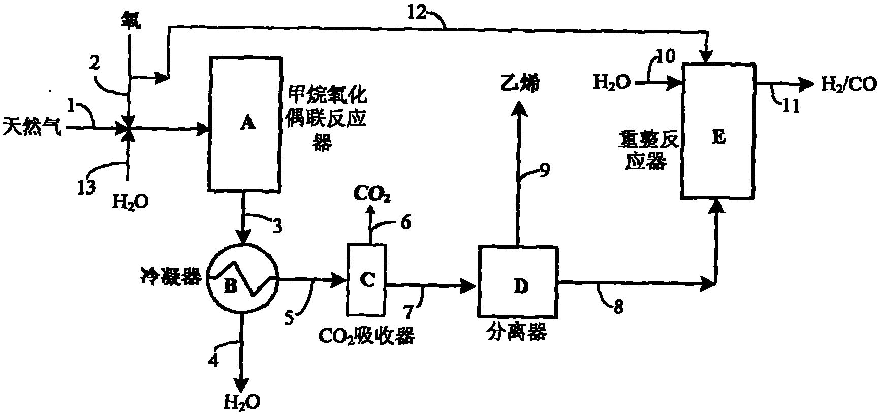
[0021] Use as attached figure 1 Shown technological process, in methane oxidative coupling OCM reactor, charge 20g Mn(2%)-Na 2 WO 4 (5%) / SiO2 2 Catalyst, loaded with 15g 9%Ni / 5%Ce / θ-Al in the reforming reactor 2 o 3 catalyst. The two reactors were heated to 800 °C and 750 °C by an external heating furnace, respectively, with 5% H 2 / N 2 After reducing the Ni catalyst for 5 h, in N 2 Continue heating to 800°C; methane 1 and O 2 2 Pass through the mass flow controller respectively, pass through the mixer at the flow rate of 8000ml / min and 2000ml / min, and enter the oxidative coupling reactor A after preheating at 400°C, and the reacted gas stream 3 is cooled to room temperature through the heat exchanger B , to remove the H generated in the reaction 2 O and high boilers 4, gas stream 5 contains 60% CH by chromatographic analysis 4 , 18% ethylene, 12% ethane, 6% CO, 3% CO 2 and 1%O 2 , into absorber C filled with 30% potassium carbonate aqueous solution, CO 2 The abs...
Embodiment 2
[0023] Attached figure 1 In the shown process, 40g Ce(2%)-Mn(2%)-Na is charged in methane oxidative coupling reactor A 2 WO 4 (5%) / SiO2 2 Catalyst, 30 g of 12% Ni / γ-Al was charged in reforming reactor E 2 o 3 catalyst. The two reactors were heated to 820 °C and 700 °C by an external heating furnace, respectively, with 5% H 2 / N 2 After reducing the Ni catalyst for 5 h, in N 2 Continue to heat reforming reactor E to 800°C; natural gas 1 and O containing 90% methane 2 2 respectively through the mass flow controller, control the flow rate of 15L / min and 4L / min, water is vaporized from 13 at a flow rate of 50ml / min, and then mixed with natural gas and O 2 Mix and enter the oxidative coupling reactor A after preheating at 400°C, the gas stream 3 after the reaction is cooled to room temperature through the cooler B, and the H produced in the reaction is removed 2 O and high boilers 4, gas stream 5 contains 58% CH by chromatographic analysis 4 , 22% ethylene, 8.5% ethane, ...
Embodiment 3
[0025]Attached figure 1 In the shown process, 10g Ce(2%)-Mn(2%)-Na 2 WO 4 (5%) / SiO2 2 Catalyst, loaded with 8 g of 12% Ni / γ-Al in reforming reactor E 2 o 3 catalyst. The reactor was heated to 800 °C and 750 °C by an external heating furnace, respectively, with 20% H 2 / N 2 After reducing the Ni catalyst for 4 h, the N 2 Continue to heat the reforming reactor to 820°C; methane 1 and O 2 2. Control the flow rate of 4L / min and 1L / min respectively through the mass flow controller, and enter the oxidative coupling reactor A after preheating at 400°C. After the reaction, the gas stream 3 is cooled to room temperature by the cooler to remove the h 2 O and high boilers, gas stream 5 contains 68% CH by chromatographic analysis 4 , 14% ethylene, 9% ethane, 5.5% CO, 2.5% CO 2 and 1%O 2 , enter the absorption tower D that ethylene adsorbent is housed after the absorber C of 30% potassium carbonate solution, the ethylene purity of separation is 92%, ethylene yield 12%; The ga...
PUM
 Abstract
Description
Claims
Application Information