Device for preparing polycrystalline silicon ingots with directional solidification microstructures
A polycrystalline silicon ingot, directional solidification technology, applied in the direction of self-solidification, polycrystalline material growth, crystal growth, etc., can solve the problems of low purity of polycrystalline silicon ingots, polycrystalline silicon pollution, etc., and achieve the effect of no pollution and high purity
- Summary
- Abstract
- Description
- Claims
- Application Information
AI Technical Summary
Problems solved by technology
Method used
Image
Examples
specific Embodiment approach 1
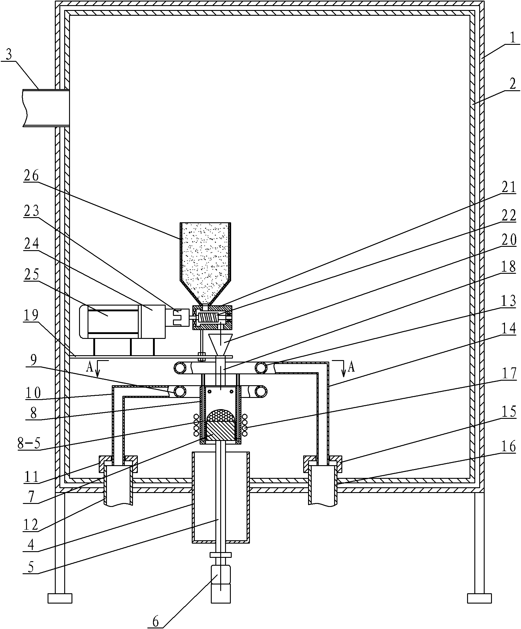
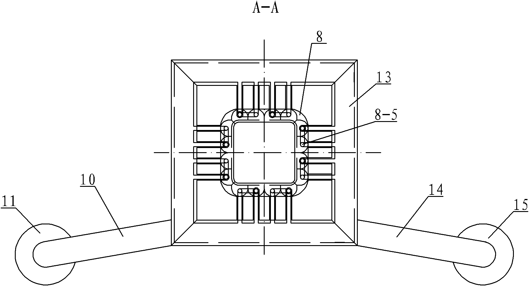
[0007] Specific implementation mode one: combine figure 1 with figure 2 Describe this embodiment, this embodiment includes a furnace body 1, a vacuum chamber 2, a vacuum pump 3, a cooler 4, a pull rod 5, a servo motor 6, a graphite base 7, a cold crucible 8, a square ring water outlet pipe 9, a water outlet connection pipe 10, First nut 11, water tank inlet pipe 12, square ring water inlet pipe 13, water inlet connection pipe 14, second nut 15, water tank outlet pipe 16, induction coil 17, graphite tube 18, support plate 19, gathering hopper 20, housing 21. Screw 22, coupling 23, adjustable gearbox 24, stepping motor 25 and hopper 26, vacuum chamber 2 is arranged in furnace body 1, vacuum pump 3 is arranged on the side wall of vacuum chamber 2, the inlet of vacuum pump 3 The end communicates with the vacuum chamber 2, the cooler 4 is arranged on the bottom plate of the furnace body 1 and the vacuum chamber 2, the pull rod 5 is arranged in the cooler 4, the lower end of the p...
specific Embodiment approach 2
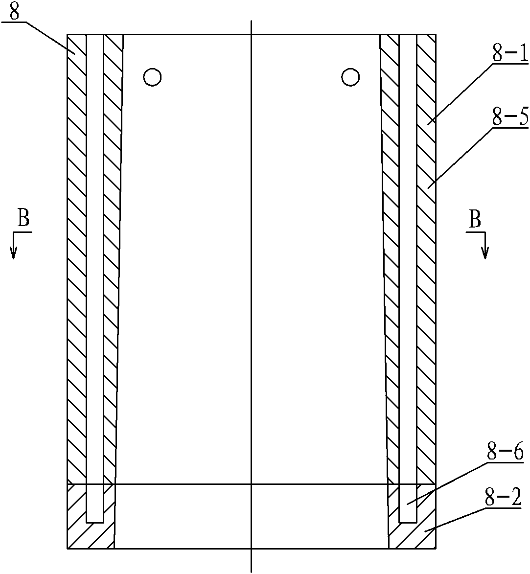
[0008] Specific implementation mode two: combination Figure 3 ~ Figure 5 Describe this embodiment, the cold crucible 8 of this embodiment is made up of upper half body 8-1, lower half body 8-2 and insulating sealing material 8-3, upper half body 8-1 and lower half body 8-2 are affixed , the cross section of the cold crucible 8 is a square ring cavity body, the upper body 8-1 is divided into sixteen cylinders 8-4, and the sixteen cylinders 8-4 are along the horizontal axis on the cross section of the cold crucible 8 Set symmetrically with the vertical axis, each cylinder 8-4 is provided with a water hole 8-5, and the side wall of the lower half 8-2 is provided with a vertical blind hole 8 at the position corresponding to the water hole 8-5 -6, each longitudinal blind hole 8-6 communicates with the corresponding water hole 8-5, sixteen blind holes 8-6 are divided into eight groups, two blind holes 8-6 in each group communicate, each adjacent two A gap T is left between the pil...
specific Embodiment approach 3
[0009] Specific implementation mode three: combination image 3 To describe this embodiment, the diameter of the inscribed circle of the square ring-shaped hollow body of the cold crucible 8 of this embodiment is smaller at the top and larger at the bottom. This design facilitates smooth and continuous pulling of the granular silicon when it solidifies and expands. Other components and connections are the same as those in the second embodiment.
[0010] Specific implementation mode four: combination Figure 5 The present embodiment will be described. In the present embodiment, the gap T is 0.3 mm to 0.8 mm, and the height H of the gap T is 100 mm to 120 mm. Such crucible split gap makes the crucible have a good magnetic permeability effect. Other components and connections are the same as those in the second embodiment.
[0011] Specific implementation mode five: combination figure 1 with image 3 The present embodiment will be described. The cold crucible 8 of the prese...
PUM
| Property | Measurement | Unit |
|---|---|---|
| Height | aaaaa | aaaaa |
| Height | aaaaa | aaaaa |
Abstract
Description
Claims
Application Information
 - R&D
- Intellectual Property
- Life Sciences
- Materials
- Tech Scout
- Unparalleled Data Quality
- Higher Quality Content
- 60% Fewer Hallucinations
Browse by: Latest US Patents, China's latest patents, Technical Efficacy Thesaurus, Application Domain, Technology Topic, Popular Technical Reports.
© 2025 PatSnap. All rights reserved.Legal|Privacy policy|Modern Slavery Act Transparency Statement|Sitemap|About US| Contact US: help@patsnap.com


