
Hydrogen energy boiler

A hydrogen energy and boiler technology, applied in the field of high-efficiency heat-exchanging hydrogen energy boilers, can solve the problems of low hydrogen production efficiency and water vapor not meeting the conditions for thermal cracking hydrogen production, so as to increase the amount of hydrogen released and overcome hydrogen production Low efficiency, good heat dissipation effect

Inactive Publication Date: 2012-09-05
沈阳威德新能源有限公司
View PDF4 Cites 1 Cited by
  • Summary
  • Abstract
  • Description
  • Claims
  • Application Information

AI Technical Summary

Problems solved by technology

[0004] The purpose of the present invention is to provide a hydrogen energy boiler, which overcomes the defects of low hydrogen production efficiency in the existing hydrogen combustion or hydrogen combustion-supporting boilers, and the water vapor cannot meet the thermal cracking hydrogen production conditions. Compared with traditional boilers, it has Reasonable design, compact structure, small size, heat exchange through the heat generated in the process of hydrogen production, and hydrogen and oxygen produced by burning hydrogen and oxygen from pyrolysis water to increase the calorific value of fuel by deflagration, so as to significantly increase the heat exchange efficiency. Effectively realize environmental protection, energy saving and consumption reduction

Method used


Image

  • Hydrogen energy boiler
  • Hydrogen energy boiler
  • Hydrogen energy boiler

Examples


Embodiment Construction

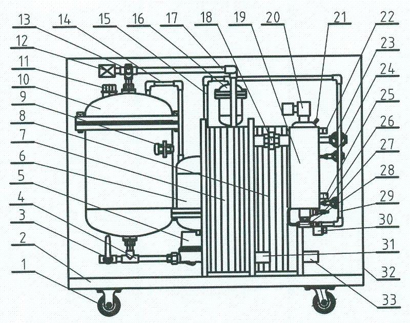
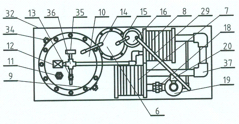
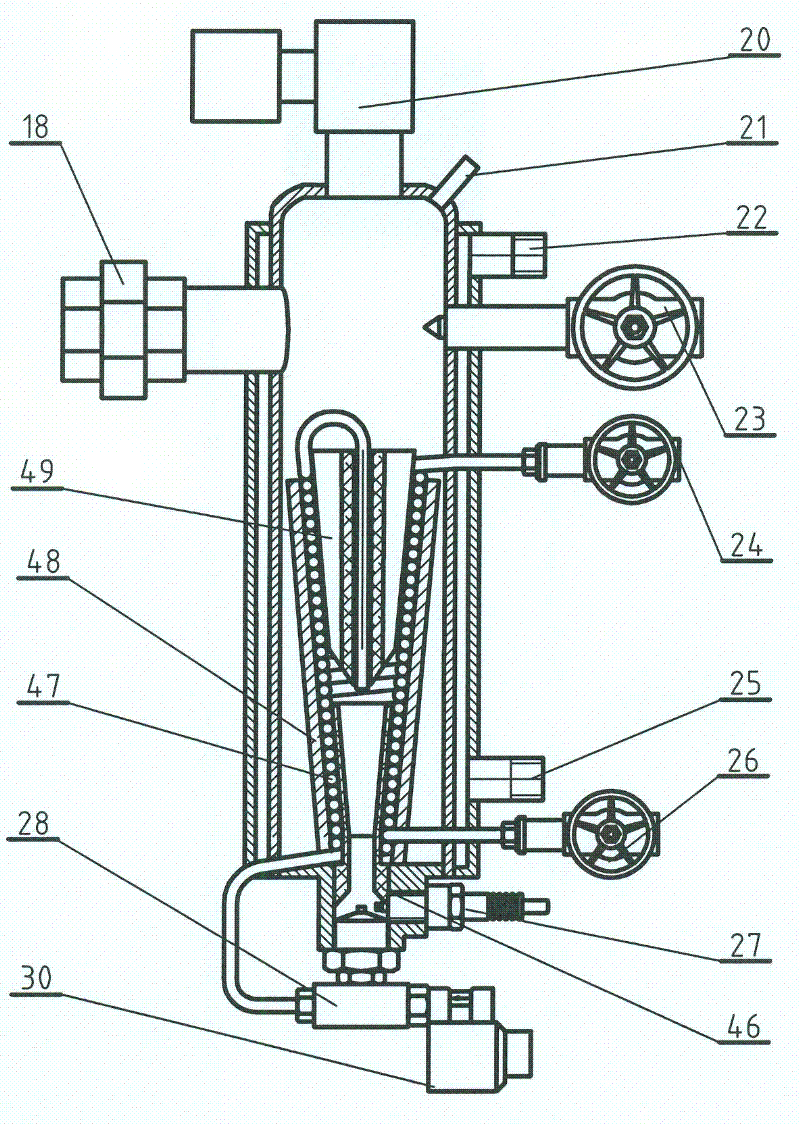
[0025] Combine below Figure 1-9 The specific structure of the present invention will be further described. This hydrogen energy boiler includes a base 2 with a casing 32 and casters 1, a hydrogen and oxygen fuel burner 19 assembled on the base, a float level gauge 11, a water replenishment check valve 13 and a safety valve 12. Hydrogen and oxygen generating tank 10, circulating water pump 5, high and low temperature heat exchangers 7 and 8, and high-frequency DC pulse power supply connected by wires, wherein the burner adopts a heat-induced hydrogen-producing burner, and a heat-induced hydrogen-producing burner has 19 shells A spiral heating tube 47 with a sheath 48 and a heat-resistant ceramic bushing 46 is arranged in the body, a heat-resistant ceramic heat island 49 assembled in the coil center of the spiral heating tube 47 and a gas nozzle 28 fixed on the base of the housing; 10. The oxygen generation tank passes through the gas-liquid separation tank 6 and the anti-temp...


PUM


Abstract

The invention relates to a hydrogen energy boiler comprising a base, a combustion engine, a hydrogen and oxygen generation tank, a water circulating pump, a high-temperature heat exchanger, a low-temperature heat exchanger and a high-frequency DC pulse power supply, wherein the base is provided with a shell and a trundle; the combustion engine is assembled on the base and takes hydrogen and oxygen as fuels; the hydrogen and oxygen generation tank is provided with a float level meter, a water replenishing one-way valve and a safety valve; and the high-frequency DC pulse power supply is connected through a conducting wire. The hydrogen energy boiler is characterized in that the combustion engine adopts a hot shock hydrogen-manufacturing combustion engine; the shell of the hot shock hydrogen-manufacturing combustion engine is internally provided with a spiral heating tube provided with a protective sleeve and a heat-resisting ceramic chamber lining; and a hot air outlet of the shell of the hot shock hydrogen-manufacturing combustion engine is communicated with a circulation heating pipeline comprising the high-temperature heat exchanger and the low-temperature heat exchanger. Compared with the traditional boiler, heat exchange is carried out through heat generated in the hydrogen-manufacturing process and the heat value of the fuels is improved by again deflagrating the hydrogen and the oxygen which are manufactured by carrying out thermal cracking on water by utilizing the combustion of the hydrogen and the oxygen, thereby the heat exchange efficiency is remarkably enhanced;and in addition, the invention effectively realizes the environmental protection, the energy saving and the consumption reduction.

Description

technical field [0001] The invention relates to a boiler using clean energy hydrogen as fuel, in particular to a high-efficiency heat exchange hydrogen energy boiler which abandons the traditional boiler structure and makes full use of pyrolysis water to generate heat energy. The heat supply of the boiler mainly uses the heat generated in the hydrogen production process for heat exchange, and uses the hydrogen and oxygen produced by burning and pyrolyzing water to increase the calorific value of the fuel, so as to significantly increase the heat exchange efficiency. Background technique [0002] At present, the development and utilization of new energy is a top priority, and research and development for the development of renewable fuels has been widely carried out in the scientific and technological circles of various countries. In recent years, due to the intensification of energy and environmental issues, the hydrogen economy has been vigorously advocated and funded by so...

Claims


Application Information

Patent Timeline
Patent Type & Authority Patents(China)
IPC IPC(8): F23C5/08F23D14/00F23D14/48C25B1/04
CPCY02E60/366Y02E60/36Y02P20/10
Inventor 李宝伟李治韩桂霞
Owner 沈阳威德新能源有限公司
Learn More