Cutting nozzle of cutting torch and processing method thereof

A processing method and technology of cutting nozzles, which are applied in combustion methods, lighting and heating equipment, gas fuel burners, etc., can solve the problems of insufficient combustion of preheated gas, unbalanced pressure, and slow cutting speed, so as to save oxygen, Easy to operate and guarantee the effect of cutting quality

Inactive Publication Date: 2011-06-15
NINGBO LONGXING WELDING CUTTING TECH STOCK
View PDF1 Cites 2 Cited by
  • Summary
  • Abstract
  • Description
  • Claims
  • Application Information

AI Technical Summary

Problems solved by technology

[0002]The cutting nozzle is an essential part of the cutting tool, generally including the cutting nozzle body, preheating hole and cutting hole, the structure of the cutting nozzle in the past existed After the mixed gas is sprayed out of the cutting nozzle, the pressure is not balanced, the preheating gas is not fully burned, the preheating is slow, and the cutting speed is slow. The cutting torch cutting nozzle with patent number 99245746.7 has a triangular or trapezoidal cross-section of the preheating hole. After the mixed gas passes through the preheating hole, it will be more dispersed, the pressure is soft, and the combustion is complete, which can increase the cutting speed and reduce the consumption of oxygen and gas. , improve work efficiency, and the surface of the object to be cut is smoother. The disadvantage is that the length of the cutting nozzle has not been adjusted in the past. The total length of the traditional cutting nozzle is generally about 90 mm. Due to the limited length of this cutting nozzle, it is suitable for steel plates. Many narrow, uneven and uneven places cannot be effectively cut. Since the length of the cutting nozzle cannot reach a certain depth, it is impossible to better preheat the steel plate and effectively cut the steel plate. Therefore, the structure of this cutting nozzle The shape still needs to be further improved and perfected

Method used


Image

  • Cutting nozzle of cutting torch and processing method thereof
  • Cutting nozzle of cutting torch and processing method thereof
  • Cutting nozzle of cutting torch and processing method thereof

Examples


Embodiment Construction

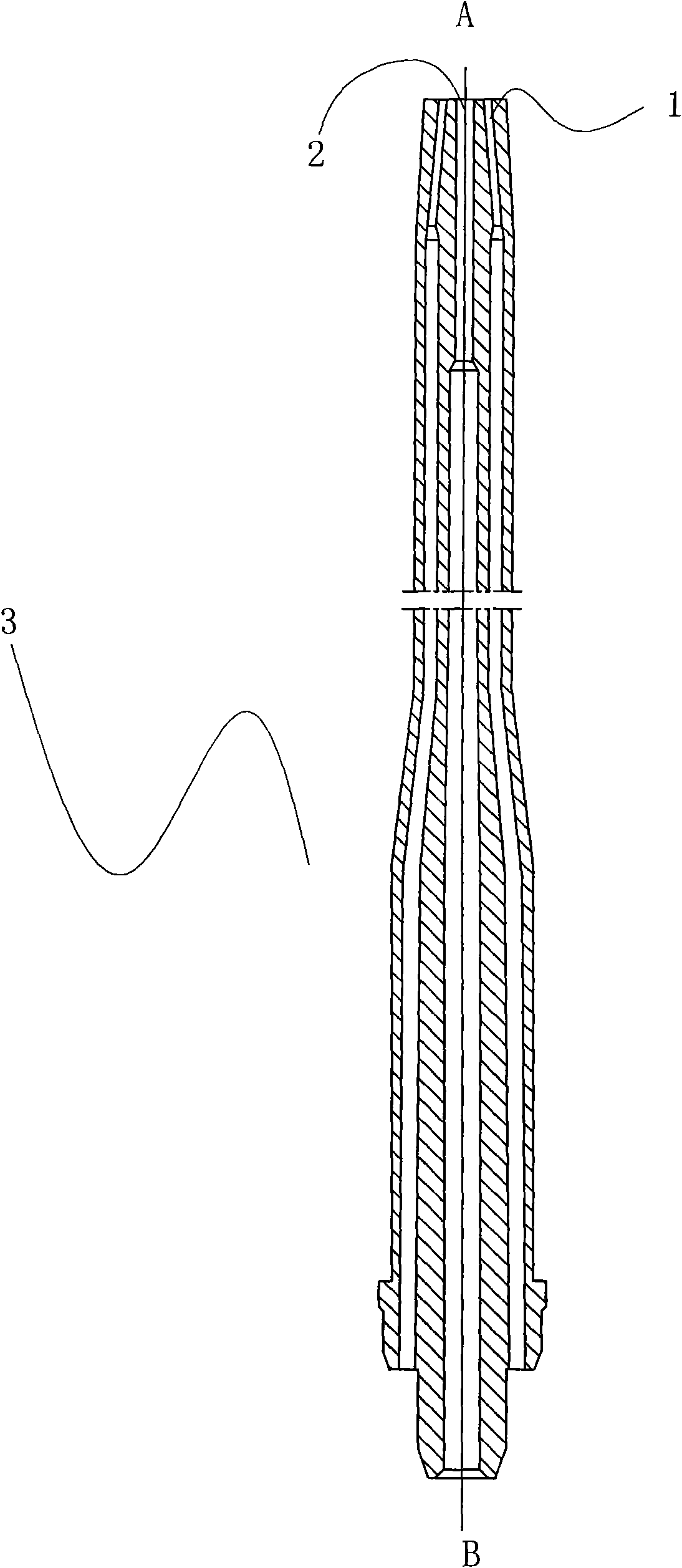
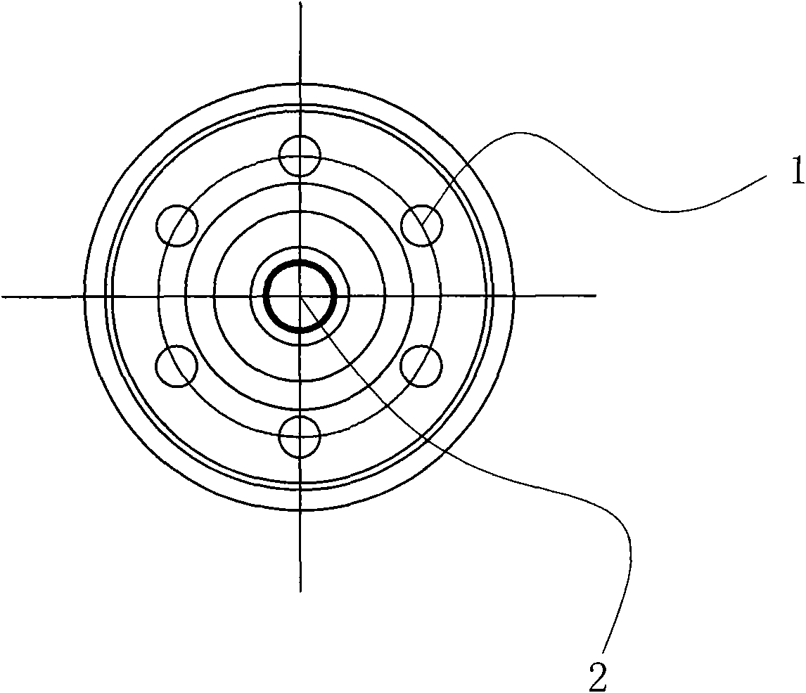
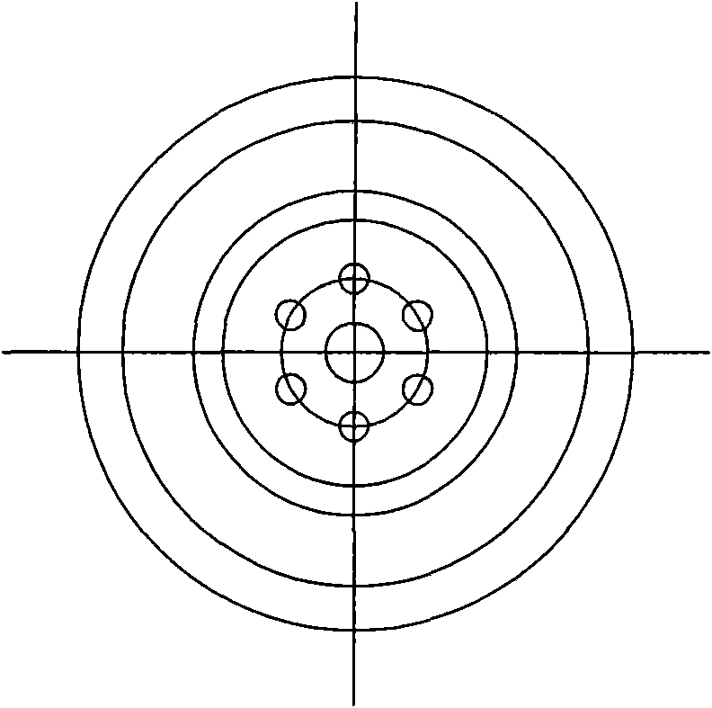
[0034] The present invention will be further described in detail below in conjunction with the accompanying drawings and embodiments.

[0035] Such as Figure 1~3 Described a kind of cutting torch cutting nozzle, comprises preheating hole 1 and cutting hole 2, and this cutting nozzle body 3 is made of T 2 Made of copper, the total length of the cutting tip body 3 is 254 mm, which is convenient for deep cutting of the workpiece. The cutting hole and the preheating hole on the cutting tip body 3 are drilled by a drilling machine or a drilling machine or a lathe.

[0036] The processing method of the above-mentioned cutting torch cutting tip body 3 comprises the following steps as follows:

[0037] 1. Cutting;

[0038] 2. Chamfering of flat two end faces;

[0039] 3. Drill 6 preheating holes φ3mm;

[0040] 4. Wear steel wire;

[0041] 5. Forging 3 times to make the pressure of 6 preheated holes φ2mm

[0042] 6. Pull steel wire;

[0043] 7. Gold processing shape, drilling a...


PUM


Abstract

The invention discloses a cutting nozzle of a cutting torch and a processing method thereof. The cutting nozzle comprises a cutting nozzle body, a preheating hole and a cutting hole, wherein the cutting nozzle body is made of T2 copper material, the total length of the cutting nozzle body is 254 millimeters, and the cutting hole and the preheating hole on the cutting nozzle body are drilled by adopting a boring machine or a drilling machine or a lathe. Compared with the prior art, the cutting nozzle can improve the preheating effect and can perform deep cutting more effectively. Meanwhile, the invention also provides the processing method for the cutting nozzle of the cutting torch. Parts are subjected to forging and drawing treatment, and processed into the preheating hole and the cutting hole in accordance with the designing and processing requirements and matching angles with the cutting torch by combining forging and metal processing techniques. The processing method is simple in process and convenient to operate.

Description

technical field [0001] The invention relates to a cutting torch cutting nozzle and a processing method thereof. Background technique [0002] The cutting nozzle is an indispensable part of the cutting tool, generally including the cutting nozzle body, the preheating hole and the cutting hole. Insufficient, slow preheating, leading to slow cutting speed and other shortcomings. At present, there is a cutting nozzle on the market that has been improved on the basis of the past. For example, the cutting torch cutting nozzle with the patent No. 99245746. The cross-section is triangular or trapezoidal, the mixed gas will be more dispersed after passing through the preheating hole, the pressure is soft, the combustion is sufficient, the cutting speed can be increased, the oxygen consumption and gas consumption are reduced, the work efficiency is improved, and the surface of the cut object is smoother. The length of the traditional cutting nozzle is not adjusted. The total length o...

Claims


Application Information

Patent Timeline
Patent Type & Authority Applications(China)
IPC IPC(8): F23D14/54
Inventor 傅佳明
Owner NINGBO LONGXING WELDING CUTTING TECH STOCK
Why Eureka
Try Eureka