Two-stage three-phase photovoltaic grid-connected system without direct-current (DC) voltage sensor and control method of system

A technology of voltage sensor and control method, applied in the field of solar photovoltaic power generation, can solve the problems of increasing system volume, reducing system reliability, increasing construction cost, etc., and achieves the effect of simplifying configuration, improving system reliability, and saving construction cost

Inactive Publication Date: 2011-06-15
STATE GRID CORP OF CHINA +2
View PDF4 Cites 25 Cited by
  • Summary
  • Abstract
  • Description
  • Claims
  • Application Information

AI Technical Summary

Problems solved by technology

[0016] It can be seen from the above that in addition to the AC voltage and current sensors necessary for grid connection, DC sensors are used more in traditional two-stage three-phase photovoltaic grid-connected systems, which not only increases the system volume, increases construction costs, but also reduces system reliability.

Method used


Image

  • Two-stage three-phase photovoltaic grid-connected system without direct-current (DC) voltage sensor and control method of system
  • Two-stage three-phase photovoltaic grid-connected system without direct-current (DC) voltage sensor and control method of system
  • Two-stage three-phase photovoltaic grid-connected system without direct-current (DC) voltage sensor and control method of system

Examples


Embodiment Construction

[0057] The specific embodiment of the present invention will be further described below in conjunction with accompanying drawing:

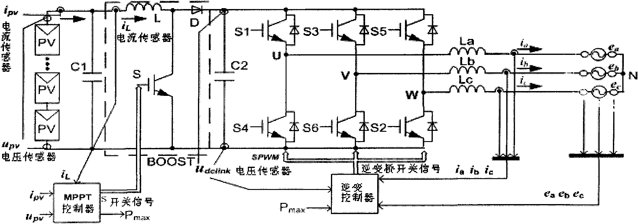
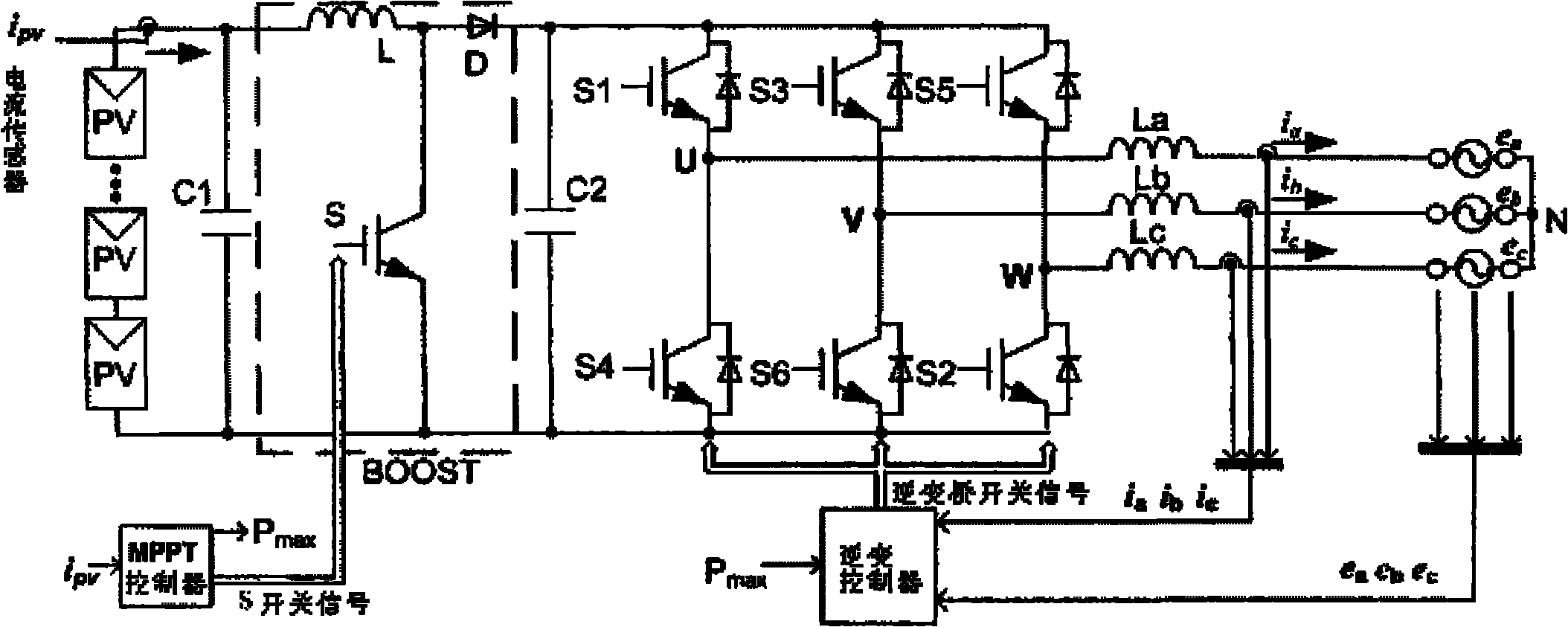
[0058] figure 2 The meaning of each symbol in is: e a 、e b 、e c is the phase voltage of the three-phase grid where the inverter is connected to the grid; i a i b i c is the three-phase grid-connected current of the photovoltaic system inverter; L a , L b , L c L is the filter inductor on the DC side; S1, S2, S3, S4, S5, and S6 are the switches of the three-phase inverter bridge, and the insulated gate transistor (IGBT) which can be turned off by parallel reverse diodes ); U, V, W are the three-phase output terminals of the grid-connected inverter; D is the Boost circuit diode; S is the Boost circuit switch tube; C 1 is the DC voltage stabilizing capacitor; C 2 is the DC link voltage stabilizing capacitor; PV is the photovoltaic panel array; i pv Output current for the photovoltaic panel array; P max The maximum power provided for the ...


PUM


Abstract

The invention relates to a two-stage three-phase photovoltaic grid-connected system without a direct-current (DC) voltage sensor and a control method of the system. The system comprises a photovoltaic (PV) cell array, a Boost circuit, an inverter circuit, a maximum power point tracking (MPPT) controller and an inverter controller, wherein the output end of the PV cell array is only provided with a current sensor. For the MPPT control in a method, a DC sensor is utilized to measure PV current; based on the correspondence of the PV voltage and the duty ratio d in the Boost circuit, d is used for calculating and controlling the PV cell array to work at a maximum power point (MPP) position; for the inverter control, based on the correspondence of the DC link voltage and the modulating signal amplitude, modulating signal amplitudes is utilized to predict a DC link voltage value in real time, and a DC link normalization coefficient is introduced so as to provide a grid-connected current reference amplitude ixref with maximum power (Pmax) after being subjected to three-phase even allocation; after being amplified by a follow-up proportional-integral (PI) controlling unit, the reference amplitude ixref is compared with a triangle carrier signal to output a pulse-width modulation (PWM) signal so as to control the switching-on / off of the inverter circuit, thus ensuring that actually output current ix can closely follows the current reference amplitude ixref, and the frequency and phase angle of the actually output current ix are identical to the frequency and phase angle of power grid voltage at a grid-connected position. According to the invention, the volume of the system can be reduced effectively, the construction cost can be reduced, and the reliability of the system can beimproved.

Description

Technical field: [0001] The invention relates to a two-stage three-phase photovoltaic grid-connected system without a DC voltage sensor and a control method, belonging to the technical field of solar photovoltaic power generation. Background technique: [0002] Among the new energy distributed power generation widely used at present, solar energy is one of the most popular new energy sources due to its inexhaustible energy source, and has a good development prospect. However, solar photovoltaic power generation is easily affected by the natural environment and has strong randomness and intermittency, that is, the output power of the system will vary greatly with time or even fluctuate in a short period of time, and the reliability of power supply of the system is greatly affected. Therefore, the effective operation mode of solar photovoltaic power generation is to merge into the public grid for power generation or to generate power with batteries. [0003] Photovoltaic grid...

Claims


Application Information

Patent Timeline
Patent Type & Authority Applications(China)
IPC IPC(8): H02J3/38
CPCY02E10/58Y02E10/563Y02E10/56
Inventor 高峰高厚磊袁建华季笑庆王邦惠柳成华刘东明康凯王玥婷鲍忠伟张颖
Owner STATE GRID CORP OF CHINA
Why Eureka
Try Eureka