Double-fed brushless motor rotor and manufacturing method thereof

A brushless motor and rotor technology, used in the manufacture of stator/rotor bodies, electrical components, electromechanical devices, etc., can solve the problems of poor magnetic coupling performance, low magnetic field modulation ability, increased motor loss, etc., and achieve good rotational dynamic balance , Conducive to heat dissipation, enhance the effect of mechanical strength

Inactive Publication Date: 2013-07-31
徐隆亚 +1
View PDF4 Cites 0 Cited by
  • Summary
  • Abstract
  • Description
  • Claims
  • Application Information

AI Technical Summary

Problems solved by technology

[0003] At present, among the reluctance rotors of double-fed brushless motors, conventional salient pole reluctance rotors and anisotropic axially laminated reluctance rotors (Axially Laminated Anisotropic, ALA for short) are commonly used, and the conventional salient pole reluctance rotor There is no magnetic barrier layer for magnetic isolation between the magnetic poles and each magnetic pole, and the rotor adopts a radial laminated structure. Theoretical research shows that the magnetic coupling performance of the conventional salient pole reluctance rotor without magnetic isolation is poor. The magnetic field modulation ability is very low, and the magnetic coupling performance and magnetic field modulation ability of the ALA rotor with a magnetic isolation magnetic circuit structure that can limit the rotor flux path are better, but because each magnetic layer of the ALA rotor is along the axial direction of the motor. With the overall tile structure, a considerable degree of eddy current will be generated in each magnetic layer when the motor is running, which will increase the loss of the motor and reduce the efficiency of the motor, and the generation of the eddy current will directly interfere with the forced magnetic field lines in the rotor. path, thereby affecting the operating performance of the motor

Method used


Image

  • Double-fed brushless motor rotor and manufacturing method thereof
  • Double-fed brushless motor rotor and manufacturing method thereof
  • Double-fed brushless motor rotor and manufacturing method thereof

Examples


Embodiment Construction

[0038] The present invention relates to the design and manufacture of a double-fed brushless motor rotor structure. For the convenience of explanation, the magnetic, electrical and mechanical characteristics and design requirements of the magnetic permeance module are described here.

[0039] 1 The characteristics and requirements of the magnetic permeability module in the magnetic circuit

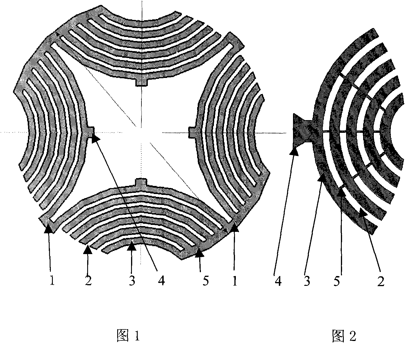
[0040] The largest possible magnetic isolation is required between the rotor magnetic permeance modules, and each magnetic permeance module has no distinction between N and S polarities. Each magnetic permeance module is formed by alternately alternating multiple magnetic permeable layers and magnetic barrier layers. The function of adding a magnetic barrier layer is to limit the magnetic flux path in each permeable module, so that the permeance in a specific direction is maximized and the permeance in a perpendicular direction is minimized.

[0041] 2 Mechanical stress characteristics an...


PUM


Abstract

The invention relates to a double-fed brushless motor rotor and a manufacturing method thereof. The rotor comprises a rotor core, a core carrier and end pressure plates; the rotor core is divided into a plurality of magnetically-independent magnetic conductance modules, each magnetic conductance module is formed by laminating laminations, the rotor core is embedded with the core carrier, and two ends of the rotor core are connected with the end pressure plates, wherein each lamination consists of a plurality of magnetic conductance layers; the adjacent magnetic conductance layers of each lamination are isolated by a magnetic barrier layer, and the magnetic barrier layer consists of air or nonmagnetic material; and the adjacent magnetic conductance layers of each lamination are connected by a connecting rib. The rotor is of a radial lamination structure, and each magnetic conductance module is nonconductive or electrically insulated, so that the eddy current loss and the magnetic hysteresis loss of the magnetic conductance modules can be reduced to minimum, and meanwhile, the magnetic force line path forced by each magnetic conductance module is not disturbed by eddy current. The manufacturing method comprises the following processes of: laminating stamped sheets of the magnetic conductance modules in the core carrier; then installing the end pressure plates and insulated fastening bolts; and finally, casting the magnetic barrier layer made of the nonmagnetic material on the whole rotor.

Description

technical field [0001] The invention relates to a doubly-fed brushless motor rotor and a manufacturing method thereof. Background technique [0002] There are two sets of independent sinusoidal distributed windings on the stator of the double-fed brushless motor, the number of poles is 2p and 2q respectively, and the number of poles of the rotor is 2p r . When the double-fed brushless motor is working, its 2p stator winding is directly connected to the grid, and the 2q stator winding is indirectly connected to the grid through the AC / DC / AC bidirectional rectifier inverter. When the double-fed brushless motor speed n r and the frequency f of the current in the two stator windings p and f q Satisfy fixed constraints: n r = 60 ( f p - f q ...

Claims


Application Information

Patent Timeline
Patent Type & Authority Patents(China)
IPC IPC(8): H02K29/00H02K1/22H02K15/02
Inventor 徐隆亚刘慧娟
Owner 徐隆亚
Why Eureka
Try Eureka