
Nozzle structure used in internal-combustion motor tail gas treatment device

A technology for exhaust gas treatment and internal combustion engine, which is applied to exhaust devices, mufflers, mechanical equipment, etc., can solve the problems of uncommon application of diesel engine post-processors, expensive manufacturing and use costs, and complex hardware structures, achieving superior performance and reducing manufacturing costs. The effect of using cost and simple hardware structure

Active Publication Date: 2011-06-22
LOTUSFAIRY POWER TECH
View PDF2 Cites 2 Cited by
  • Summary
  • Abstract
  • Description
  • Claims
  • Application Information

AI Technical Summary

Problems solved by technology

Although the rest can have relatively complete and reliable functions and have commercial products on the market, they have the following inherent shortcomings: the hardware structure is too complex, too large, and the energy consumption is high, the life is short, and the manufacturing cost is expensive, etc.
Also because of this, the application of diesel engine post-processors is not common all over the world.

Method used


Image

  • Nozzle structure used in internal-combustion motor tail gas treatment device
  • Nozzle structure used in internal-combustion motor tail gas treatment device
  • Nozzle structure used in internal-combustion motor tail gas treatment device

Examples


Embodiment Construction

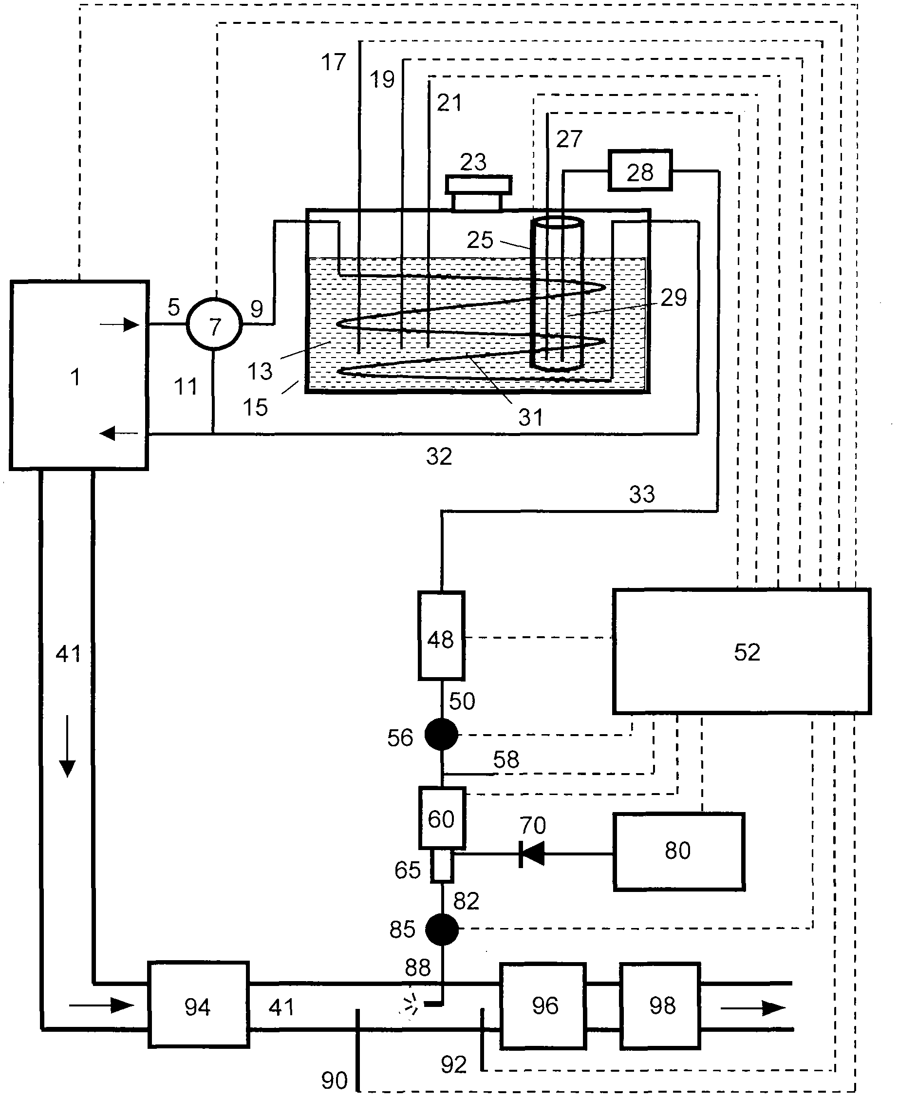
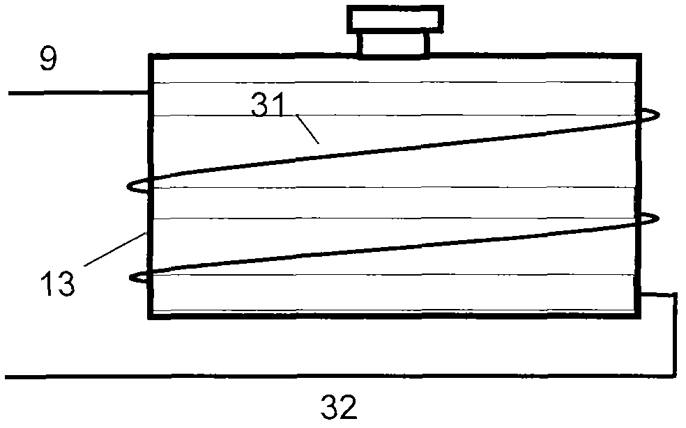
[0112] figure 1 It shows a form of the main structure of the aftertreatment device for purifying engine exhaust according to the present invention. The device includes additive 13, additive supply system, catalyst system 94, 96, 98 and electronic control unit (ECU) 52. The additive supply system includes a liquid tank 15, an additive solution supply line composed of a liquid path and a gas path, an air supply system, a system cleaning function, and a heating system. The electronic controller 52 includes on-vehicle monitoring and diagnosis (OBD) and communication functions.

[0113] (1) The engine 1 can be a diesel engine or a leanburn gasoline engine. The engine 1 establishes contact with the electronic controller 52 through various interfaces and transmits various information data about the engine to the electronic controller, including speed, load, coolant temperature, exhaust temperature, pressure and so on. The electronic controller 52 will rely on these information data to...


PUM


Abstract

The invention relates to a nozzle structure used in an internal-combustion motor tail gas treatment device. The nozzle structure provided by the invention comprises a nozzle and a nozzle flow guider, wherein the tail end of the nozzle is provided with the nozzle flow guider. The nozzle structure provided by the invention has the advantages that the tail gas of an engine or other foreign matters can be prevented from entering the nozzle, also obstruction matters in the nozzle or the outlet of the nozzle can be removed, and also the spraying is ensured to be more reliable.

Description

[0001] The application for the present invention is a divisional application of the invention application filed by the applicant of the present invention on December 4, 2006 with the application number 200610161817.2 and the invention title "internal combustion engine exhaust purification method and device". Technical field [0002] This invention relates to internal combustion engine emission control, specifically, an aftertreatment system including an internal combustion engine exhaust purification method and device. Background technique [0003] Due to the urgent need to improve fuel economy, the application of diesel engines and leanburn gasoline engines has rapidly increased in recent years. However, because the combustion chamber and its exhaust gas contain too much oxygen, these engines emit a large amount of nitrogen oxides, which makes the method using ordinary three-way catalysts unable to work. In response to this problem, people have proposed a variety of post-treatmen...

Claims


Application Information

Patent Timeline
Patent Type & Authority Applications(China)
IPC IPC(8): F01N3/20F01N3/24
Inventor 李平吴靖雄郭进端
Owner LOTUSFAIRY POWER TECH
Learn More