Multiple input multiple output (MIMO) array antenna

An array antenna, multi-output technology, applied in the direction of antenna, resonant antenna, antenna coupling, etc., to achieve the effect of simple implementation, small size and stable performance

Inactive Publication Date: 2011-06-22
ZTE CORP
View PDF4 Cites 42 Cited by
  • Summary
  • Abstract
  • Description
  • Claims
  • Application Information

AI Technical Summary

Problems solved by technology

However, in a small-sized mobile communication system, limited by the size of the receiver or transmitter, and the size of the whole machine, it is impossible to provide a half-wavelength spacing. Therefore, placing multiple devices with little correlation in a limited space MIMO antennas are difficult, which makes the removal of strong coupling between antennas one of the urgent problems to be solved

Method used


Image

  • Multiple input multiple output (MIMO) array antenna
  • Multiple input multiple output (MIMO) array antenna
  • Multiple input multiple output (MIMO) array antenna

Examples


Embodiment Construction

[0027] MIMO antennas are transmitters and receivers in wireless communications that use multiple antennas to form an array. It is difficult to apply MIMO antennas in small-sized mobile communication systems. The invention provides a weak coupling MIMO array antenna for a small-sized mobile communication terminal, which can overcome size limitation.

[0028] First introduce the technical principle of this method invention below

[0029] The coupling between the two antennas will affect each other, reflected in the Y matrix is ​​Y 12 =Y 21 ≠0, therefore, decoupling can eliminate Y in a specific way 12 and Y 21 .

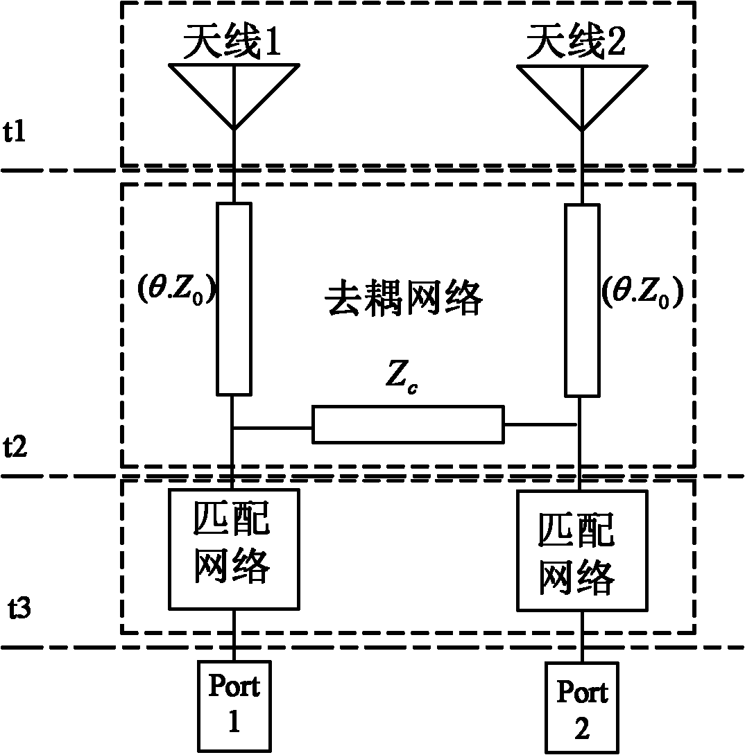
[0030] figure 1 The structure diagram of the decoupling principle mentioned in this paper is given, by figure 1 It can be seen that the decoupling network is divided into two parts: one part is two sections with an angle of θ and a characteristic impedance of Z 0 part of the transmission line is impedance Z c circuit structure. A matching network can be selec...


PUM


Abstract

The invention discloses a multiple input multiple output (MIMO) array antenna, comprising a dielectric material plate, antenna units, floors and a decoupling network, wherein the antenna units are arranged at one end of the dielectric material plate and distributed at two sides of the center line of the dielectric material plate symmetrically so as to form an antenna array; the antenna units are connected with the dielectric material plate by framing members and are also connected with the decoupling network by shrapnels or soldered dots; the decoupling network is printed on the front side of the dielectric material plate, which is used for eliminating the coupling among the antenna units; and the floors are printed on the back side of the dielectric material plate. In the array antenna, the antenna units and the decoupling network are small in size, thus being applied to mobile terminals with small size; the decoupling network is of a microstrip line structure, thus being simple to realize and stable in performance; and the convex floors are used, thus being easy to adjust the impedance match of the antenna and realizing wide band work of the antenna.

Description

technical field [0001] The invention relates to the field of wireless communication antennas, in particular to a MIMO (Multiple Input Multiple Output, Multiple Input Multiple Output) array antenna. Background technique [0002] Insufficient spectrum resources seriously hinder the development of wireless communication technology. With the development of wireless communication in the direction of large capacity, high transmission rate and high reliability, this bottleneck effect becomes more and more obvious. How to maximize the use of limited spectrum resources has become a hot topic in current research. In the past two decades, many new technologies have been proposed, but neither conventional transmit diversity or receive diversity methods, nor smart antenna technology can meet today's demand for large channel capacity and high-quality communications, while MIMO Technology is undoubtedly the most potential and most advantageous of many methods. [0003] MIMO technology is...

Claims


Application Information

Patent Timeline
Patent Type & Authority Applications(China)
IPC IPC(8): H01Q1/12H01Q1/48H01Q1/52H01Q9/30H01Q21/00
CPCH01Q9/30H01Q1/52H01Q21/28H01Q1/38H01Q1/12H01Q1/243H01Q1/48H01Q1/521H01Q9/42H01Q21/00
Inventor 张璐江晖艾浩刘英姜林涛
Owner ZTE CORP
Why Eureka
Try Eureka