Synchronous dust removing device

A technology of dust removal device and synchronous transmission, applied in laser welding equipment, electrical components, climate sustainability, etc., can solve the problems of shortened life of wiring aging motor, low dust removal efficiency, polluted equipment, etc., and achieve good dust removal effect and dust collection. Small area, high dust removal effect

Inactive Publication Date: 2011-06-29
东莞宏威薄膜真空技术有限公司
View PDF8 Cites 9 Cited by
  • Summary
  • Abstract
  • Description
  • Claims
  • Application Information

AI Technical Summary

Problems solved by technology

[0004] Using the above-mentioned first high-power exhaust fan closed environment drainage method to collect and process the dust generated during the marking process has certain effects on the surface film of small-area amorphous silicon solar panels and low-speed marking lines, but for such as amorphous silicon When the film substrate of thin-film solar panels is a large-area glass substrate of 1100 mm × 1400 mm, the dust cannot be completely absorbed, resulting in low dust removal efficiency. On the one hand, it is difficult to form a large closed space to generate sufficient airflow; On the other hand, it is necessary to introduce a high-power exhaust fan to realize the function of dust removal, and the high-power exhaust fan will cause greater noise pollution and increase energy consumption. At the same time, it is not easy to dissipate heat in a closed space, and the long

Method used


Image

  • Synchronous dust removing device
  • Synchronous dust removing device
  • Synchronous dust removing device

Examples


Example Embodiment

[0017] The preferred embodiments of the present invention will now be described with reference to the accompanying drawings. Similar element numbers in the accompanying drawings represent similar elements.

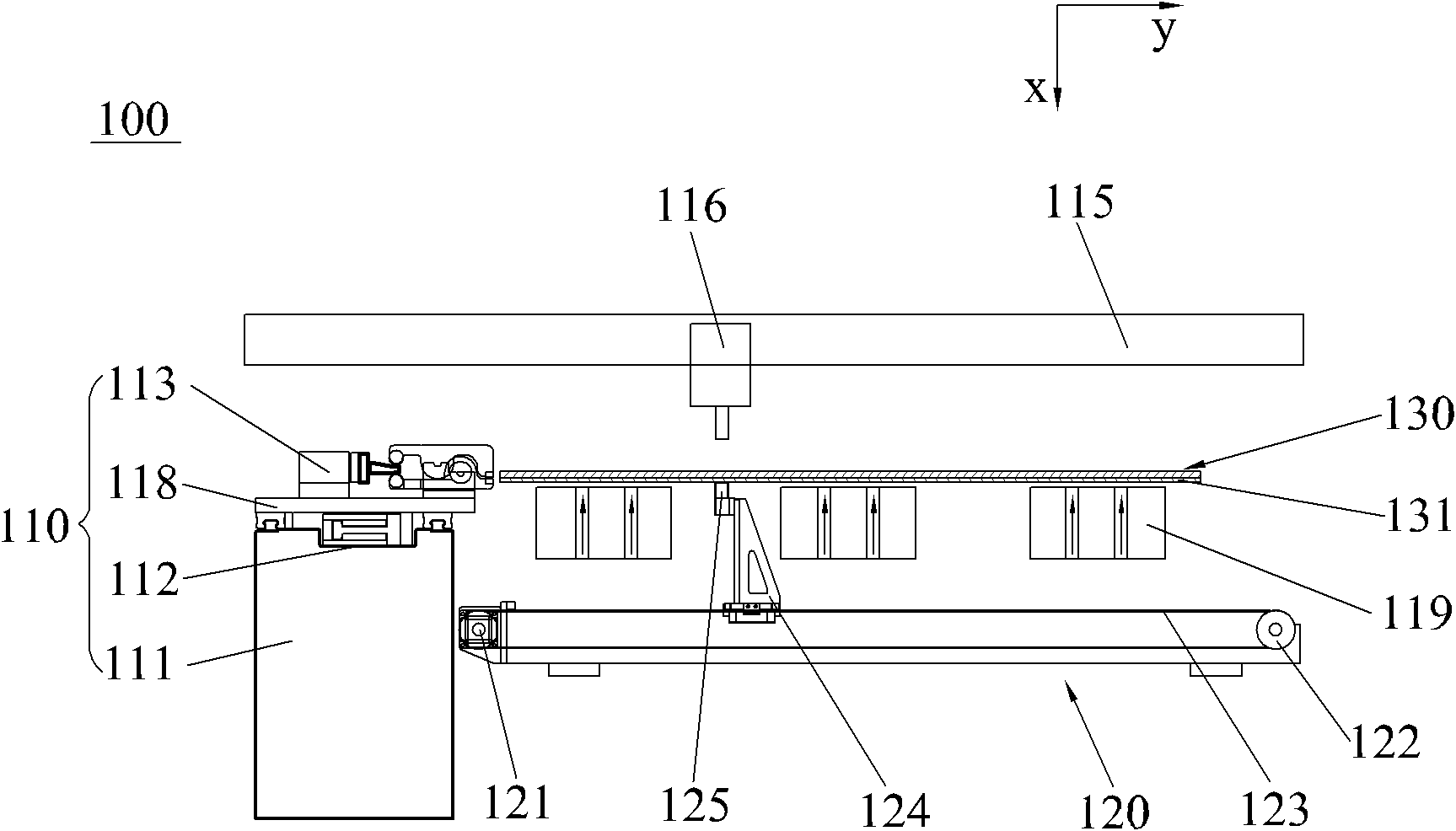
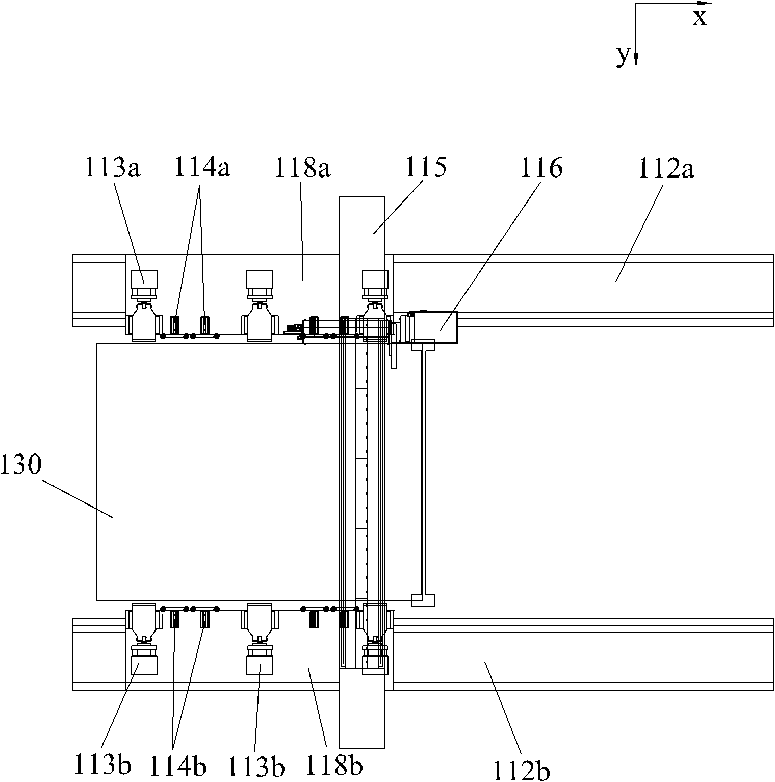
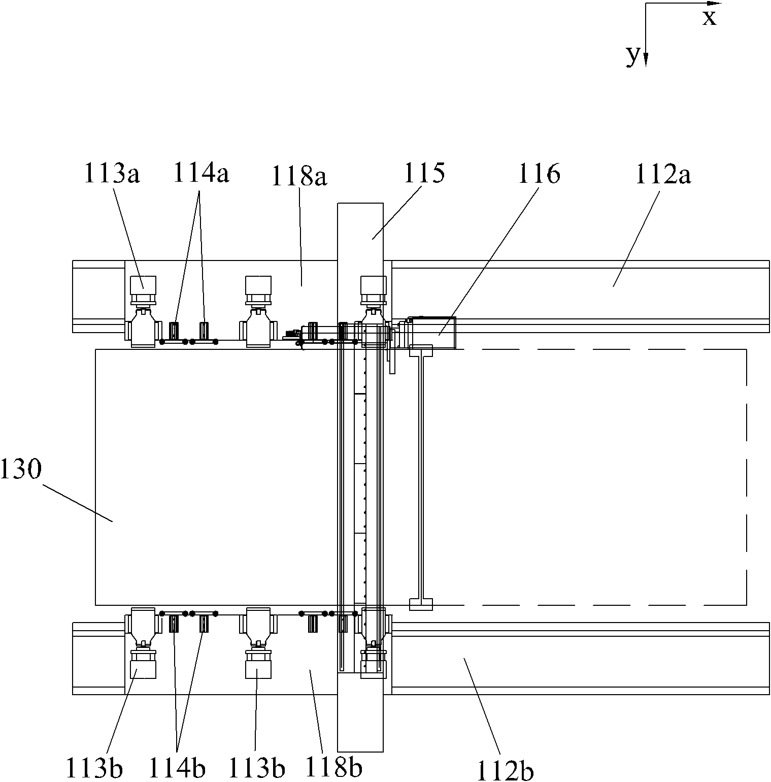
[0018] Such as figure 1 , figure 2 As shown, the synchronous dust removal device 100 of the present invention includes a control unit (not shown), a processing unit 110, and a dust removal unit 120. The processing unit 110 and the dust removal unit 120 are both connected to the control unit; the processing unit 110 includes an installation platform 111 and a laser track 115 , Laser moving mechanism (not shown), laser generator 116 and air floating platform 119. Two parallel gripper rails 112a, 112b are provided on the installation platform 111, and sliding blocks 118a, 112b are slidably connected to the gripper rail 112a. The upper slide is connected with a sliding block 118b, the gripper 113a is connected to the gripper rail 112a through the sliding block 118a, the gripper 1...


PUM


Abstract

The invention discloses a synchronous dust removing device. The device comprises a control unit, a processing unit and a dust removing unit, wherein the processing unit comprises an air floatation platform, a laser track, a laser moving mechanism and a laser generator; an amorphous silicon solar glass substrate is carried above the air flotation platform and a film layer faces downwards; the laser generator is slidably arranged on the laser track; a light outlet hole of the laser generator is positioned above the amorphous silicon solar glass substrate; the dust removing unit comprises a negative pressure dust collector and a synchronous transmission mechanism; the synchronous transmission mechanism is arranged below the air flotation platform; and a negative pressure suction nozzle of the negative pressure dust collector is formed on the synchronous transmission mechanism, is opposite to the light outlet hole of the laser generator, and is driven by the synchronous transmission mechanism to synchronously move together with the light outlet hole of the laser generator, so that the etching and the dust removing of the film layer are synchronized. The device has a better dust removing effect; meanwhile, since the negative pressure suction nozzle is extremely small, and the dust collection area is small, a good dust removing effect can be achieved by a low-power fan.

Description

technical field [0001] The invention relates to a dust removal device, in particular to a dust removal device when a laser generator etches an amorphous silicon solar glass substrate. Background technique [0002] In the process of solar panel preparation, especially in the preparation process of amorphous silicon solar glass substrates, a laser generator needs to be used for laser etching after each coating. If the dust generated during the etching process is not cleaned after etching, the dust will It will be deposited on the etching tank and the battery board, and the dust will be covered in the next coating process, which will cause a short circuit on the circuit layout on the battery board; at the same time, the dust deposited on the glass surface will also affect the film in the next evaporation process Thickness and uniformity, thereby reducing the photoelectric conversion rate of the entire board. [0003] At present, there are two main ways to collect the dust gene...

Claims


Application Information

Patent Timeline
IPC IPC(8): B23K26/42B23K26/36H01L31/18B23K26/362B23K26/70
CPCY02P70/50
Inventor 杨明生范继良刘惠森蓝劾余超平王曼媛王勇
Owner 东莞宏威薄膜真空技术有限公司
Why Eureka
Try Eureka