Method and device for monitoring state of ballastless track structure through fibber bragg grating sensing

A fiber grating and ballastless track technology, applied in track, track maintenance, road, etc., can solve the problems of complex installation, poor stability, complex system, etc., and achieve the effect of strong anti-interference ability, good stability and high sensitivity

Active Publication Date: 2011-06-29
WUHAN UNIV OF TECH
View PDF5 Cites 28 Cited by
  • Summary
  • Abstract
  • Description
  • Claims
  • Application Information

AI Technical Summary

Problems solved by technology

Compared with developed countries, there is still a certain gap in the performance and application standards of rail inspection vehicles in my country. Some key sensors have not been localized, and the detection data of rail inspection vehicles cannot be fully utilized.
The existing GPS positioning and displacement testing technology is applied to the state monitoring of ballastless track and slab ballast bed structure. It can only test the displacement between the monitoring point and the reference point. The multi-point testing system is complicated, and the temperature of the track cannot be monitored and the accuracy is limited.
The image capture method and laser positioning scanning method are applied to the state monitoring of ballastless track and slab ballast bed structure. The installation is complicated, the signal processing is difficult, the temperature cannot be monitored, and the displacemen

Method used


Image

  • Method and device for monitoring state of ballastless track structure through fibber bragg grating sensing
  • Method and device for monitoring state of ballastless track structure through fibber bragg grating sensing

Examples


specific Embodiment approach

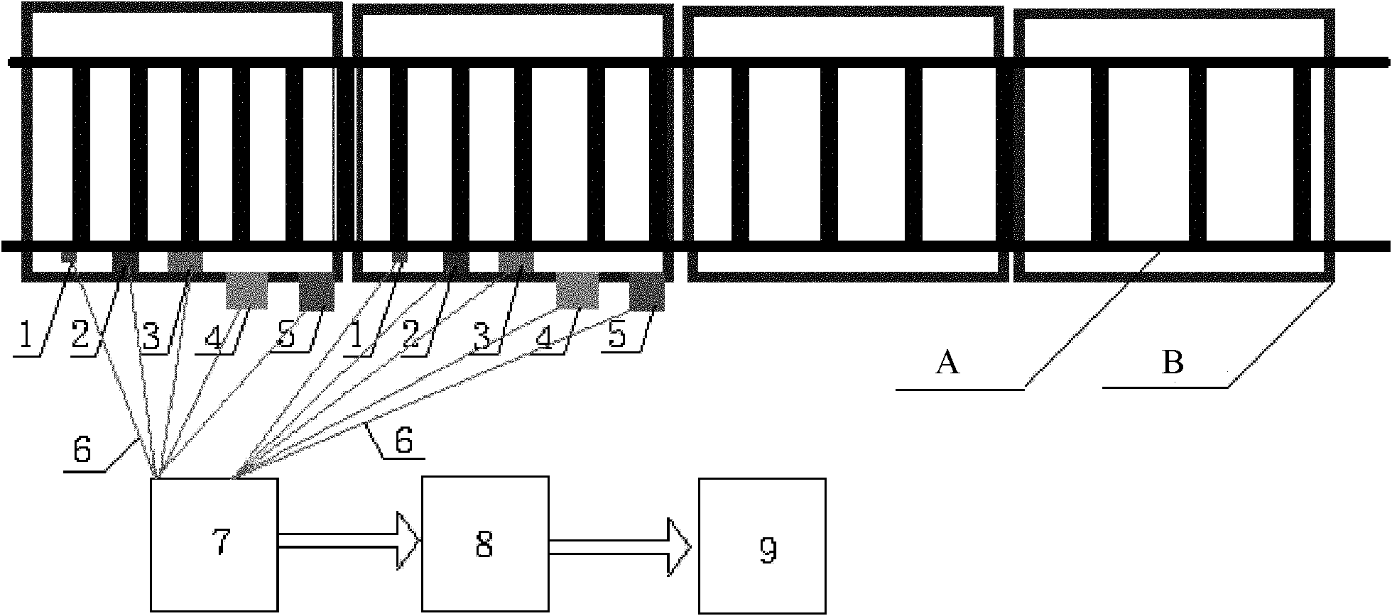
[0020] 1: The system device includes M optical fiber grating rail temperature and strain combined sensors 1, N optical fiber grating rail lateral displacement, longitudinal displacement and vertical displacement combined sensors 2, P optical fiber grating rail lateral acceleration, longitudinal acceleration and vertical acceleration combination Sensor 3, Q fiber grating plate ballast bed lateral displacement, longitudinal displacement and vertical displacement combined sensor 4, R fiber grating plate ballast bed lateral acceleration, longitudinal acceleration and vertical acceleration combined sensor 5, sensor shell, fixing device, auxiliary device, Transmission optical fiber 6, multi-channel fiber grating wavelength demodulator 7, data processing terminal 8, and alarm device 9.

[0021] 2: Fiber Bragg grating rail temperature and strain combined sensor 1. Fiber Bragg grating rail lateral displacement, longitudinal displacement and vertical displacement combined sensor 2. Fiber...


PUM


Abstract

The invention discloses a device for monitoring a state of a ballastless track structure through fibber bragg grating sensing, which comprises M fibber bragg grating steel rail temperature and stress combined sensors, N fibber bragg grating steel rail horizontal displacement, longitudinal displacement and vertical displacement combined sensors, P fibber bragg grating steel rail horizontal acceleration, longitudinal acceleration and vertical acceleration combined sensors, Q fibber bragg grating plate type ballast horizontal displacement, longitudinal displacement and vertical displacement combined sensors, R fibber bragg grating plate type ballast horizontal acceleration, longitudinal acceleration and vertical acceleration combined sensors, a multi-channel fibber bragg grating wavelength demodulator, a data processing terminal and an alarm device. The combined sensors are arranged at state monitoring points of the ballastless track structure of a rapid transit railway, and are directly contacted with the steel rail, the ballast and a base or are fixed by a supporting layer, wavelength output signals of various sensors are respectively transmitted to the demodulator through a transmission fiber and then are transmitted to the real-time data processing terminal and the alarm device, and if an abnormal state is monitored, the alarm device is started for early warning.

Description

Technical field: [0001] The invention belongs to the field of fiber grating sensing technology applied to the construction, operation, maintenance and maintenance of ballastless track structures of high-speed railways, and relates to temperature, strain, lateral displacement, A monitoring method and device for longitudinal displacement, vertical displacement, lateral acceleration, longitudinal acceleration, and vertical acceleration state. Background technique: [0002] According to the national "medium and long-term railway network plan (adjusted in 2008)", in the future, my country will comprehensively build a four-vertical and four-horizontal high-speed railway network covering major population and industrial clusters. By 2020, the total mileage will exceed 16,000 kilometers At the same time, Chinese enterprises have undertaken railway construction projects in more than 50 countries and regions, covering more than 50 countries and regions in Asia, Africa, Oceania and the A...

Claims


Application Information

Patent Timeline
IPC IPC(8): E01B35/00E01B35/12G08B21/18
Inventor 姜德生潘建军李维来王立新
Owner WUHAN UNIV OF TECH
Why Eureka
Try Eureka