Cooling device

A refrigeration device and refrigerant technology, which is applied in refrigerators, refrigeration components, refrigeration and liquefaction, and can solve problems such as complicated control of valve devices

Active Publication Date: 2011-06-29
SANYO ELECTRIC CO LTD
View PDF4 Cites 5 Cited by
  • Summary
  • Abstract
  • Description
  • Claims
  • Application Information

AI Technical Summary

Problems solved by technology

[0010] However, as described above, when the waste heat recovery heat exchanger is installed on the front stage side of the gas cooler, there is a problem that the control of the valve device on the separation cycle side is complicated in consideration of the control on the water heater side.

Method used


Image

  • Cooling device
  • Cooling device
  • Cooling device

Examples


Embodiment Construction

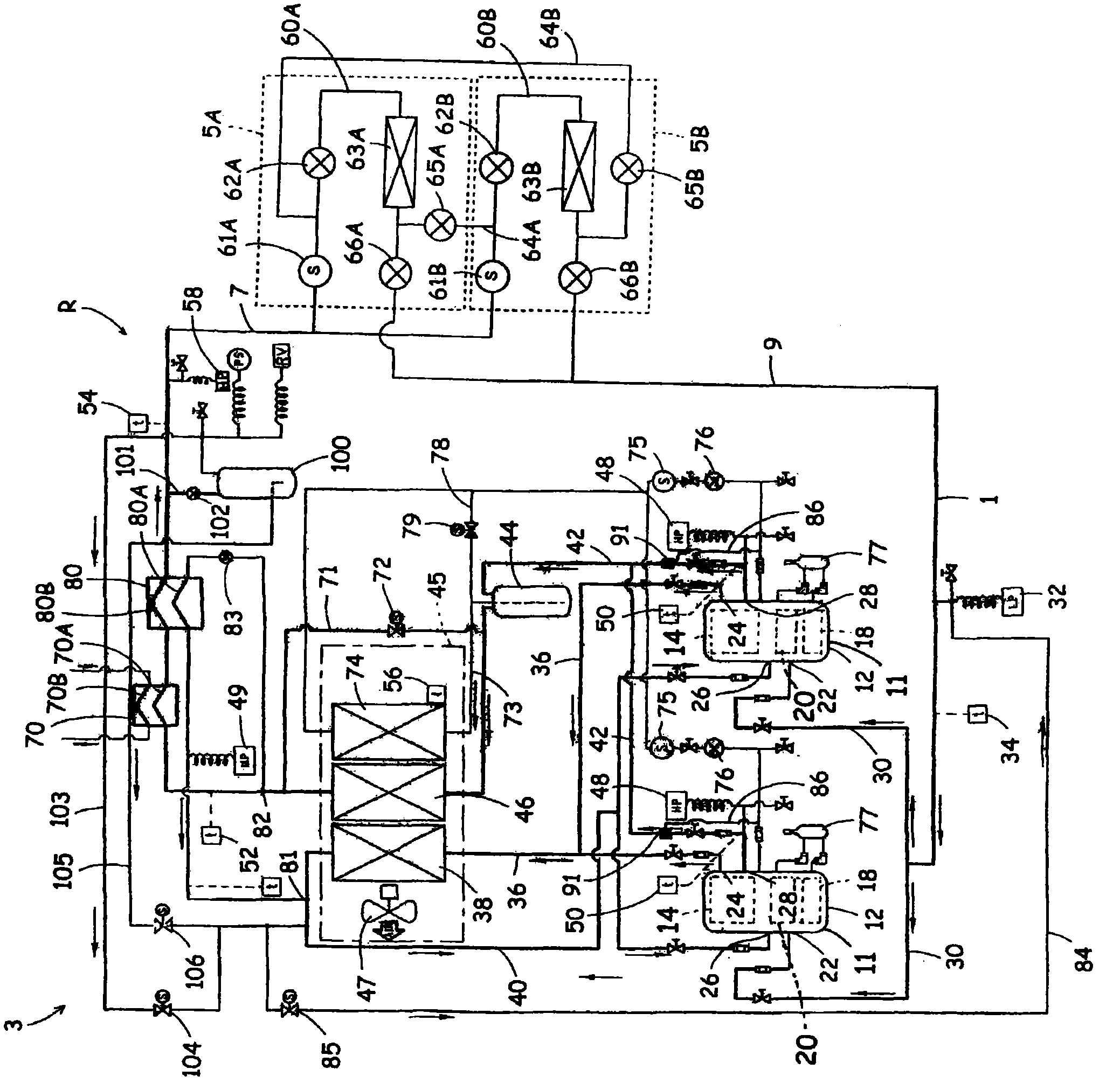
[0089] Hereinafter, embodiments of the present invention will be described with reference to the drawings. figure 1 This is a refrigerant circuit diagram of the refrigeration apparatus R according to the embodiment of the present invention. The refrigeration apparatus R of this embodiment includes a refrigerator unit 3 and a plurality of showcase units 5A, 5B. The refrigerator unit 3 and the showcase units 5A, 5B are connected by refrigerant pipes 7 and 9 to form a predetermined refrigeration cycle.

[0090] In this refrigeration cycle, carbon dioxide whose high-pressure side refrigerant pressure (high-pressure pressure) is higher than its critical pressure (supercritical) is used as a refrigerant. This carbon dioxide refrigerant is a natural refrigerant that is beneficial to the global environment and considers flammability and toxicity. In addition, existing oils such as mineral oil (mineral oil), alkylbenzene oil, ether oil, ester oil, and PAG (polyalkylene glycol) are used as...


PUM


Abstract

The invention provides a cooling device which is provided with a separation recycling device with a supercritical pressure formed at a high-pressure side, can provide hot water by using waste heat, and enables high-efficient operation of a refrigeration cycle. The cooling device (R) of the invention is provided with a separation recycling device with a supercritical pressure formed at the high-pressure side; the cooling device (R) is provided with a waste heat recovery heat exchanger (70), and the waste heat recovery heat exchanger (70) is provided with a waste heat recovery medium flow path (70B) and a refrigerant flow path (70A); and the cooling device (R) allows the second refrigerant flow (main refrigerant flow towards an evaporator) which flows out from a gas cooler (46) and has not flowed into an intermediate heat exchanger (80) forming the separation recycling device to flow into the refrigerant flow path (70A) of the waste heat recovery heat exchanger (70).

Description

Technical field [0001] The present invention relates to a refrigeration device in which a compression mechanism, a gas cooler, a throttling mechanism, and an evaporator constitute a refrigerant circuit and the high-pressure side becomes a supercritical pressure. Background technique [0002] At present, in this kind of refrigeration device, the refrigeration cycle is constituted by a compression mechanism, a gas cooler, a throttle mechanism, etc. The refrigerant compressed by the compression mechanism radiates heat through the gas cooler and is decompressed by the throttle mechanism, and then evaporates through the evaporator , So as to use the evaporation of the refrigerant to cool the surrounding air. In recent years, in such refrigeration devices, it has been impossible to use Freon-based refrigerants due to natural environmental problems and the like. Therefore, a refrigeration device that uses carbon dioxide as a natural refrigerant as a substitute for Freon refrigerant has...

Claims


Application Information

Patent Timeline
Patent Type & Authority Applications(China)
IPC IPC(8): F25B29/00
CPCY02A30/274F25B49/02F25B2600/25F25B2400/072F25B2400/075F25B2400/04F25B41/20
Inventor 三原一彦佐佐木英孝长谷川说川久保贤大竹雅久
Owner SANYO ELECTRIC CO LTD
Why Eureka
Try Eureka