Intelligent charging method and device for battery management system of electric vehicle
A battery management system and intelligent charging technology, applied in electric vehicle charging technology, battery circuit devices, electric vehicles, etc., can solve the problems of poor charging effect and low charging efficiency, and achieve the elimination of potential safety hazards, avoid overcharge damage, and avoid effect of life
- Summary
- Abstract
- Description
- Claims
- Application Information
AI Technical Summary
Problems solved by technology
Method used
Image


Examples
Embodiment 1
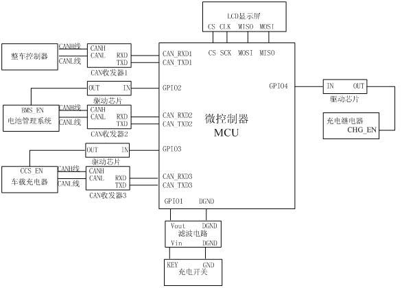
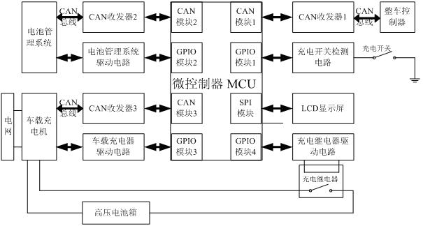
[0048] Such as figure 1 As shown: the smart charging device is mainly composed of a microcontroller (MCU-Micro Control Unit), a controller area network (CAN-Controller Area Network) transceiver, a charging switch detection circuit, and a battery management system (BMS-Battery Management System) drive circuit , car charger drive circuit, charging relay drive circuit and LCD display. Among them, the GPIO-General Purpose Input Output (GPIO-General Purpose Input Output) interface 1 of the MCU cooperates with the charging switch detection circuit to collect the charging switch signal to determine whether to enter the smart charging mode. After entering the smart charging mode, GPIO2 of the MCU enables the BMS through the driving circuit of the battery management system, and GPIO3 enables the on-board charger through the driving circuit of the on-board charger. At the same time, the CAN communication module 1 of the MCU is connected to the CAN bus interface of the vehicle controll...
Embodiment 2
[0050] Such as figure 2 As shown: the signal receiving pin CAN_RXD1 and the signal transmitting pin CAN_TXD1 of the CAN communication module 1 of the MCU are connected with the signal receiving pin RXD and the signal transmitting pin TXD of the CAN transceiver 1 to complete the TTL level transmission of the CAN bus; The CANH terminal and the CANL terminal of the CAN transceiver 1 are connected with the CAN bus interface CANH terminal and the CANL terminal of the VCU to complete the differential level transmission of the CAN bus, thus realizing the conversion between the TTL level and the differential level.
[0051] The signal receiving pin CAN_RXD2 and the signal sending pin CAN_TXD2 of the CAN communication module 2 of the MCU are connected with the signal receiving pin RXD and the signal sending pin TXD of the CAN transceiver 2 to complete the TTL level transmission of the CAN bus; the CAN transceiver The CANH terminal and CANL terminal of 2 are connected to the CAN bus in...
PUM
 Abstract
Description
Claims
Application Information
 - Generate Ideas
- Intellectual Property
- Life Sciences
- Materials
- Tech Scout
- Unparalleled Data Quality
- Higher Quality Content
- 60% Fewer Hallucinations
Browse by: Latest US Patents, China's latest patents, Technical Efficacy Thesaurus, Application Domain, Technology Topic, Popular Technical Reports.
© 2025 PatSnap. All rights reserved.Legal|Privacy policy|Modern Slavery Act Transparency Statement|Sitemap|About US| Contact US: help@patsnap.com