
Low-phase noise broadband quadrature voltage controlled oscillator

A voltage-controlled oscillator, low phase noise technology, applied in power oscillators, automatic power control, electrical components, etc., can solve the problems of deteriorating QVCO phase noise, limited phase shift, low operating frequency, etc., and achieve increased tuning range, improved linearity, and effects of low phase noise

Inactive Publication Date: 2011-07-06
FUDAN UNIV
View PDF0 Cites 23 Cited by
  • Summary
  • Abstract
  • Description
  • Claims
  • Application Information

AI Technical Summary

Problems solved by technology

The power dissipation of the snubber and the mismatch of passive resistive capacitors are the main disadvantages of this method
The last method is to use QVCO directly. The design of QVCO is more difficult than that of VCO, and the area will be correspondingly larger, but its operating frequency is lower than that of the two-way frequency method. In this method, the additional power consumption comes from an additional VCO
[0003] The traditional transistor-coupled quadrature voltage-controlled oscillator has the following three problems: (1) Dual-mode oscillation problem
(2) The deterioration of the quality factor Q value of the resonant network, which in turn deteriorates the phase noise of the QVCO
Literature [1][2] proposed two methods of introducing a phase shift network, but the phase shift introduced by the cascode structure of literature [1] is limited, only about 20 degrees, although it can solve the problem of dual-mode oscillation, but The improvement of the phase noise is limited. The access method of the coupling tube in literature [2] is a capacitive coupling common-gate stage. Since the input resistance of the common-gate stage is small, this access method will easily deteriorate the Q value of the LC resonant network.

Method used


Image

  • Low-phase noise broadband quadrature voltage controlled oscillator
  • Low-phase noise broadband quadrature voltage controlled oscillator
  • Low-phase noise broadband quadrature voltage controlled oscillator

Examples


Embodiment 1

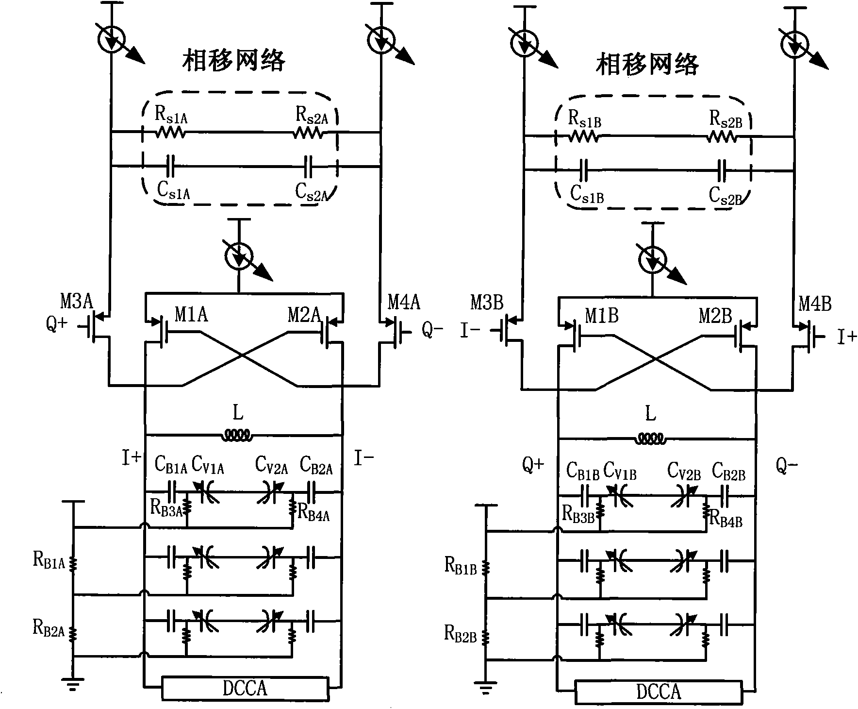
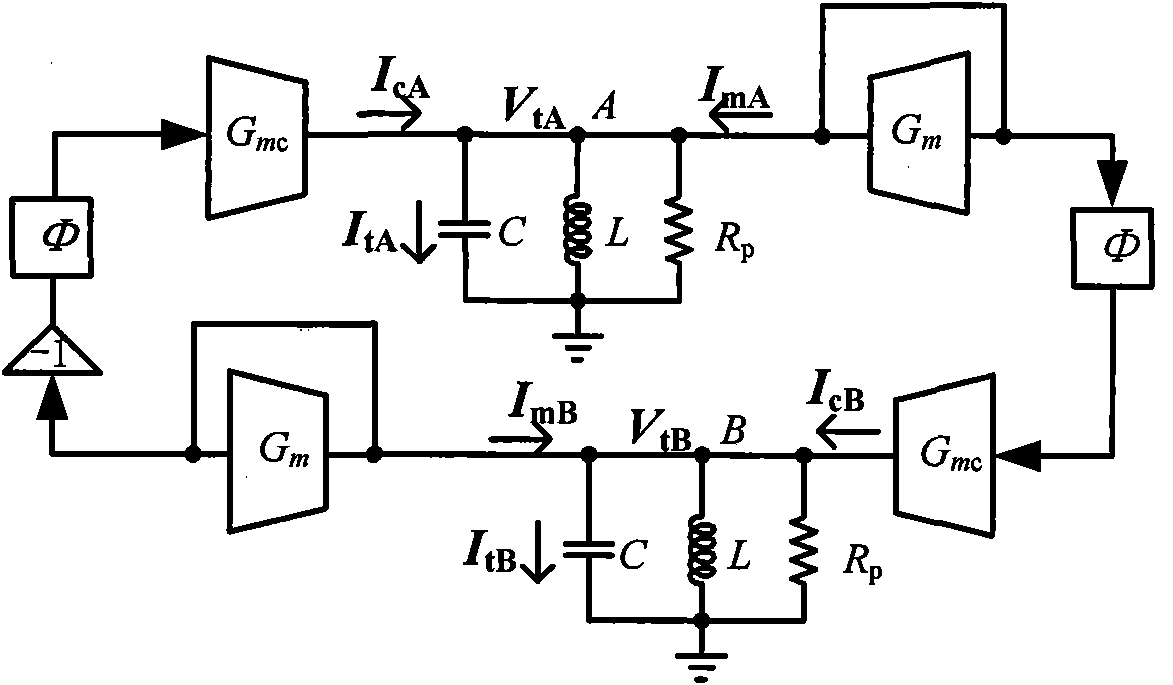
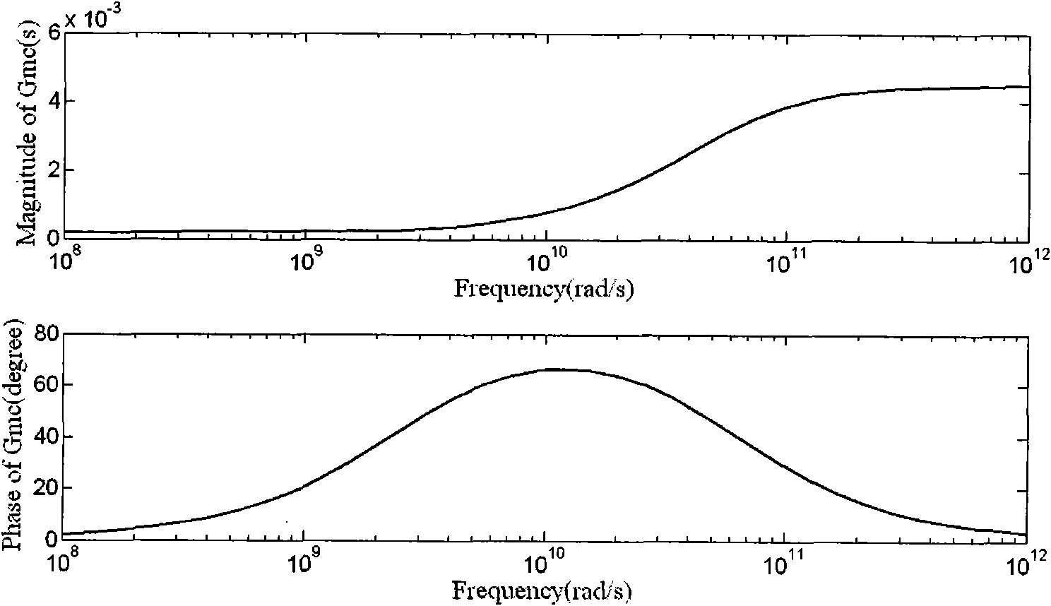
[0030] figure 1 The structure of the present invention is shown, wherein M1A and M2A, M1B and M2B respectively provide negative resistance for two VCOs; M3A and M4A, M3B and M4B provide orthogonal coupling paths for two VCOs. The phase relationship of the output signal and its coupling mode are marked in the figure. figure 2 gives figure 1 A linear model of a circuit. to combine figure 1 and figure 2 It can be seen that the negative resistance tube provides energy for the resonant network to maintain the oscillation, and the coupling tube injects the oscillating voltage of one VCO into the other VCO in the form of current, so that the phases of the two oscillating voltages are in an orthogonal relationship. figure 2 Middle G m Represents the effective transconductance of the negative resistance tube, G mc Indicates the effective transconductance of the coupled tube. Φ represents the phase shift of the signal between the two VCO couplings, which is determined by fig...


PUM


Abstract

The invention belongs to the technical field of radio frequency wireless receiver integrated circuits, and relates to a quadrature voltage controlled oscillator in a wireless receiver integrated circuit. In the quadrature voltage controlled oscillator, the phase noise performance of the quadrature voltage controlled oscillator circuit is improved and the output phase mismatch is reduced by improving a coupling mode of the conventional quadrature voltage controlled oscillator and introducing a phase shift network at the source end of a coupling tube. By using a linearly changed an accumulation-type metal-oxide semiconductor (MOS) variable capacitor array, the linearity of a tuning curve of a quadrature voltage controlled oscillator (QVCO) is greatly improved so that the tuning range of a control voltage is increased. Because a bias current of the QVCO is variable, a relatively constant output oscillating voltage amplitude can be maintained; therefore, a low phase noise can be obtained by the QVCO in a broad output frequency range.

Description

technical field [0001] The invention belongs to the technical field of radio frequency wireless receiver integrated circuits, and in particular relates to a quadrature voltage-controlled oscillator used in a frequency synthesizer of a wireless receiver. Background technique [0002] The development of digital signal processing technology has had an important impact on digital communication. In digital communication, various complex digital modulation methods are applied to complete high-quality wireless signal transmission. It involves operations such as modulation, demodulation, and detection of complex signals. Reflected in the circuit of the radio frequency receiving and transmitting part, the frequency synthesizer is required to provide the local oscillation signal of the quadrature I and Q signals so that the radio frequency front-end circuit can complete the processing of complex signals. Studies have shown that for frequency synthesizers of certain communication pro...

Claims


Application Information

Patent Timeline
Patent Type & Authority Applications(China)
IPC IPC(8): H03L7/099H03B5/14
CPCH03B27/00
Inventor 李巍黄德平周谨李宁任俊彦
Owner FUDAN UNIV
Learn More